1 General
1.0.1 is to implement the relevant national laws, regulations and regulations in the design of silicon solar cell factories to achieve the objectives of environmental protection, advanced technology, economical rationality and quality assurance, as well as water saving, energy saving, land saving, and material saving. Develop this specification.
1.0.2 This specification applies to the design of new, expanded and rebuilt silicon solar cell factories.
1.0.3 The design of a silicon solar cell factory shall meet the following requirements:
1 It is necessary to rationally use resources and protect the environment, and to prevent pollution and harm to the environment from exhaust gas, waste water, waste residue, dust, harmful gases, radioactive substances, and noise, vibration, and electromagnetic radiation generated during production and construction activities.
2 According to the characteristics of the production process, actively adopt new technologies, new equipment, and new materials.
3 The design shall create necessary conditions for construction and installation, maintenance and management, commissioning and maintenance, and safe production in the future.
4 should meet the requirements of building fire protection.
1.0.4 The design of a silicon solar cell factory shall, in addition to complying with this specification, comply with the relevant national standards.
2 Terms
2.0.1 silicon solar cell silicon solar cell
Solar cells based on crystalline silicon are also called silicon solar cells or crystalline silicon cells.
2.0.2 acid/alkali exhaust
The exhaust ventilation medium contains partial discharge of acid vapors and alkaline substances in the process.
2.0.3 Organic exhaust
The exhaust gas contains organic solvent vapors in the process of local exhaust.
2.0.4 process exhaust tail gas
The production equipment discharges the process gas containing silane, ammonia, etc. that needs to be processed.
2.0.5 technical shaft technical shaft
The collective name of vertical wells such as cable wells, pipeline wells, exhaust ducts, exhaust passages, and garbage roads.
2.0.6 reverse osmosis dense water
After the raw water is concentrated by the reverse osmosis device, the ionic liquid has a high ion content and does not crystallize.
2.0.7 Gas station gas station
Place the air compressor and vacuum pump in the room.
2.0.8 chiller station
Place the freezer and its associated equipment in the room.
2.0.9 Special gas
Silane, ammonia, and a smaller amount of carbon tetrafluoride gas.
2.0.10 bulk gas bulk gas
In the production of solar cell products, it is a generic name for nitrogen gas and oxygen gas that are used in large amounts as reaction gas, shielding gas, and purge gas.
2.0.11 Final resistance final resistance
Air filter dust accumulation, resistance increases, when the resistance increases to a specified value, the filter is scrapped, the resistance value of filter scrap.
2.0.12 Substation Substation
Refers to the 110kV or below AC power supply voltage transformer after the power transformer, and the power supply of electrical devices and its supporting buildings.
2.0.13 uninterruptible power supply (uninterruptible power system)
An energy storage device is provided. When the main power supply is interrupted, the stored energy is converted and output through the inverter circuit, and a constant voltage constant frequency power supply system is continuously provided for the load.
3 overall design
3.1 Site Selection
3.1.1 Silicon solar cell plant location selection should be combined with regional long-term planning, and determined based on a comprehensive comparison of local economic and technical conditions.
3.1.2 Factories should choose areas with low concentrations of atmospheric dust and harmful gases.
3.1.3 Factories should choose areas with large environmental capacity and relatively complete municipal wastewater treatment facilities.
3.1.4 Factories should choose areas where municipal gas, electricity, and water supply are sufficient and transportation is convenient.
3.2 General layout
3.2.1 The plant layout of the silicon solar cell factory should be rationally laid out according to the functional areas such as the process production system, power assist system, gas system, chemical system, three-waste treatment system, warehouse office system, and living system.
3.2.2 The flow of people out of the plant area and logistics should be set separately.
3.2.3 The plant area should be set up according to the local planning and design requirements.
3.2.4 The loading and unloading area of ​​the factory shall be provided with enough trucks to enter and exit the venue, and shall not occupy the fire exits.
3.2.5 Class A and B goods stores and Class A and B gas stations should be set independently.
3.2.6 The circular firefighting lane should be set in the factory area.
3.2.7 The road surface of the factory shall use materials with good overall performance and low dust emission.
3.2.8 In addition to meeting the planning requirements, plant greening should also be conducive to maintaining a good environment within the plant area.
3.3 Personnel purification and material purification
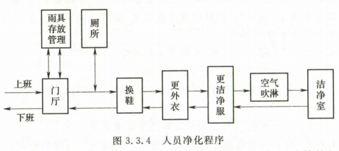
3.3.1 Personnel purification rooms should include changing shoes, storing coats, replacing clean work clothes and other rooms. Storage rooms for rain gear, toilets, management rooms, rest rooms, and other rooms, such as air showers, air locks, work clothes washing rooms, and drying rooms, can be set as needed.
3.3.2 Personnel purification rooms and living room settings should meet the following requirements:
1 The staff of the personnel purification room should have a net shoe facility.
2 The coat storage cabinet should be one cabinet per person according to the design number of the clean room (area).
3 Toilets and showers should be set up before entering the staff room.
3.3.3 The design of the silicon solar cell factory air shower room shall meet the following requirements:
1 It is advisable to have an air shower in the clean room (area). When there is no air shower, an air lock chamber should be provided.
2 The air shower room should be adjacent to the clean work clothes changing room.
3Single person air shower room should be set according to the maximum class size for every 30 people. When the maximum class usage number is more than 30 people, 2 or more single person showering rooms can be arranged in parallel, or use more than one person to shower. room.
4 By-pass door shall be provided on one side of the air shower.
3.3.4 Personnel purification rooms and living rooms should be arranged in accordance with Figure 3.3.4 according to the product production process and air cleanliness level requirements.
3.3.5 The clean room (area) material out of the population, should be based on the nature of the material, size and other characteristics of the design.
3.3.6 The clean room should be designed for removable metal panels for handling equipment and temporary buffers that are easy to set up when handling equipment. The location should be set to ensure that the clean room is free from contamination and the convenience of the equipment's transportation lines.
3.4 Process Design
3.4.1 The process division of the silicon solar cell plant should be set up with personnel out of the population and materials out of the population.
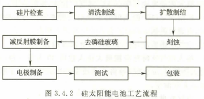
3.4.2 The process zoning of the silicon solar cell plant shall be arranged according to the production process flow of the product. The routine arrangement may be carried out according to Figure 3.4.2.
3.4.3 The production environment and power quality should meet the requirements of the silicon solar cell production process.
3.4.4 The process layout shall comply with the requirements for the installation and maintenance of production process equipment. The transportation passages, installation ports, inspection ports and purification facilities shall be provided, and the arrangement shall be reasonable, compact and conducive to production operations.
3.4.5 The selection of process equipment should meet the following requirements:
1 Select equipment with low energy consumption and low emissions.
2 should choose a strong compatibility, can be upgraded to automated production or high degree of automation equipment.
3 Equipment that can meet product quality and process requirements should be selected.
3.4.6 Silicon solar cell production line design should adopt the continuous production and operation mode.
4 Construction and Structure
4.1 General provisions
4.1.1 The building function of the silicon solar cell plant should meet the requirements of the production process.
4.1.2 The design of the plant shall meet the requirements for the flow of people and logistics; the planning of the auxiliary facilities shall meet the overall layout of the process.
4.1.3 The building construction plane and space layout should be flexible, and the main structure should adopt large space and large span column nets.
4.1.4 The materials and shapes of the building envelope shall conform to the requirements of energy-saving insulation, fire prevention, moisture prevention, and low dust production.
4.1.5 The durability of the main structure of the factory shall be coordinated with the level of indoor equipment and decoration. The main structure shall have the properties of fire prevention, temperature deformation control and non-uniform settlement reduction.
4.1.6 deformation joints of the workshop should not cross the clean area; when the deformation joint of the workshop must pass through the clean area, corresponding measures should be taken.
4.1.7 Technical workshops or technical clips should be set up in the production area of ​​the plant, and inspection and repair channels should be set up in the technical interlayers or technical clips. When a vertical pipeline crossing the floor needs to be concealed, a technical shaft should be set.
4.1.8 The trenches in the production area with cleanliness requirements should be designed as dark trenches, and the trenches should be treated with anti-corrosion treatment.
4.1.9 The ground at the logistics channel should be flat and there should be no bumps.
4.1.10 Gas station rooms, air-conditioning rooms, etc. shall be equipped with noise elimination, sound insulation and vibration reduction measures.
4.1.11 The design of chemical warehouses and tank farms in the factory area shall comply with the current national standards ((Fire Protection Code for Building Design) GB50016).
4.1.12 The setting of the chemical intermediate warehouse in the factory shall meet the following requirements:
1 The chemical intermediate warehouse shall be set in a separate room, and the intermediate warehouses for storing Class A, B and C chemicals shall be separated from the workshop by firewalls and non-combustible floors with a fire endurance of not less than 1.5h. Rely on the exterior wall.
2 Chemical intermediate warehouses shall be classified and stored according to the physical and chemical properties of the chemicals; when the nature of the materials does not allow storage in the same warehouse, physical walls shall be used to separate them, and the population shall be set for each.
The reserves of intermediate warehouses of Class A and B chemicals should not exceed the required consumption of 24h, and the volume of Class C liquid intermediate tanks should not exceed 1m3.
4.1.13 The special gas in the workshop shall be designed in accordance with the intermediate warehouse of class A and B. The pressure relief ratio of the special gas storing silane shall not be less than 0.11.
4.1.14 The floor mat of the factory should be equipped with a single-layer two-way reinforcement mesh, and the damp layer should be protected against moisture.
4.1.15 Equivalently distributed live loads for the floor of a factory building shall be determined in accordance with the load requirements for the installation and maintenance of industrial equipment. When there is a lack of information, they may be determined in accordance with Table 4.1.
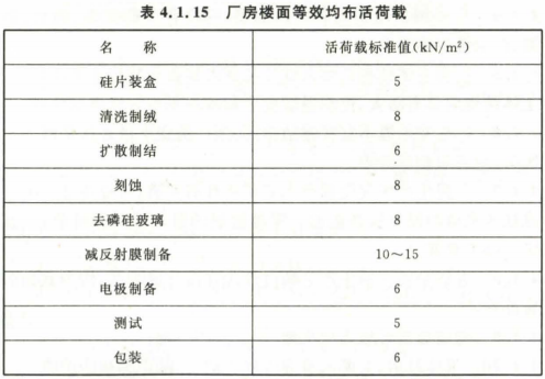
Note: 1 Other loads not listed in the table shall be selected in accordance with the relevant provisions of the current national standard "Code for the Loading of Building Structure" GB 50009.
2 The combined value coefficient of live load is 1.0, the frequency coefficient is 0.9, and the quasi-permanent coefficient is 0.8.
3 The list of live loads does not include the wall weight.
4 When designing main beams, walls, columns and foundations, the list of live loads shall be reduced. The reduction factor may be 0.6-0.8.
4.2 Building fire prevention
4.2.1 The fire hazard category of the silicon solar cell production plant shall be Class C, and the fire resistance rating of the plant shall not be lower than Class II.
4.2.2 The ceiling, walls and sandwich material in the clean area of ​​the factory shall be non-burning bodies. The fire-resistance limit of the ceiling and siding shall not be less than 0.5h, but the fire-resistance limit of the evacuation aisle partition shall not be less than 1.0h.
4.2.3 Between the clean production area and the general production area within a fire partition, there shall be partition walls or ceilings that are not to be burned, and the fire resistance limit shall not be less than 1.0h. The gaps around the pipelines that pass through partitions or ceilings should be tightly filled with fire-proof plugging material.
4.2.4 The internal partition wall of the clean area can be partitioned to the ceiling of the ceiling.
4.2.5 The shaft of the technical shaft shall be non-burning and its fire resistance limit shall not be less than 1.0h. The fire-resistance limit of the inspection door on the borehole wall shall not be less than 0.sh; in the shaft floor at each floor, the non-combustion body equivalent to the fire limit of the floor shall be used for horizontal fire separation; the gap around the pipeline passing through horizontal fire separation shall be Use fire blocking material to close the plug tightly.
4.2.6 Safety exits shall be arranged in a decentralized manner, and the population shall not be purified by means of showering, etc., and clear evacuation signs shall be set up for safety exits.
4.2.7 The safety evacuation distance shall be determined in conjunction with the layout of the process equipment, and shall comply with the relevant provisions of the current national standard "Code for the Fire Protection of Architectural Design" GBSo016.
4.3 interior decoration
4.3.1 The building envelope and interior decoration of the plant should use materials with good airtightness and small deformation.
4.3.2 The floor of the factory building shall meet the production process requirements of smoothness, no dust, and glare avoidance.
4.3.3 The cleanliness of the interior walls and ceilings of the plant shall be protected from dust and glare. Brick wall plastering walls shall not be used.
4.3.4 The windows in the clean area should not be equipped with windowsills.
4.3.5 The closed door of the clean room should be opened in a room with high air cleanliness, and a door closer should be added. The observation window should be set on the closed door.
4.3.6 The combustion performance of the decoration materials selected for the design shall comply with the relevant provisions of the current national standard "Code for the Fire Protection of Interior Decoration for Buildings" GB5o222.
4.3.7 Process requirements When the clean room needs to be made of an anti-static floor, it can be designed in accordance with the current national standard “Design Code for Electronic Industrial Cleanroom†GBSo472 Anti-static environment.
5 Heating Ventilation, Air Conditioning and Purification
5.1 General provisions
5.1.1 The design plan shall be determined according to the technological requirements, characteristics of the building, existing energy conditions, etc., and shall be effective, economical, reasonable and energy-saving.
5.1.2 Ventilation, air conditioning and purification systems shall be designed to meet the requirements of the production process for the production environment and shall be adapted to the needs of different production loads.
5.1.3 The setting of the heating system of the factory shall comply with the relevant provisions of the current national standard "Code for the design of heating, ventilation and air conditioning" GBSOo19.
5.1.4 Antifreeze measures shall be taken for pipelines and equipment that are located in severe cold areas and cold areas and that may create a risk of freezing.
5.1.5 Radiator heating should not be provided in areas where the cleanliness is better than Class 8.
5.1.6 The wind speed of the main air duct shall not be designed to be greater than gm/5. The main branch air speed shall be 3m/s-6m/s, and the branch air speed shall not be greater than 4m/s.
5.2 Ventilation
5.2.1 The ventilation system should be set up in accordance with personnel safety, hygiene and production processes.
5.2.2 The process equipment in the production plant that continuously produces harmful gases shall be provided with a local exhaust device.
5.2.3 When meeting one of the following conditions, the local exhaust system should be set separately:
1 Exhaust gas mixture can produce or exacerbate corrosiveness, toxicity, combustion explosion risk and cross-contamination.
2 Rooms and equipment that emit highly toxic substances.
3 After the exhaust medium is mixed, the steam can easily condense and accumulate dust.
5.2.4 Exhaust air system in the clean area shall take measures to prevent outdoor air inflow, and the exhaust system shall be installed on the inlet side of the fan.
5.2.5 The exhaust system containing flammable and explosive substances should be set separately from the general exhaust, and fire and explosion prevention and safety discharge measures should be taken.
5.2.6 If the concentration and discharge of harmful substances in the exhausted air exceed the national or local standards, the harmless treatment shall be carried out. The concentration and the discharge after treatment shall comply with the relevant regulations of the current national and local environmental protection authorities.
5.2.7 The height of outlets of acid-alkali air exhaust and organic air exhaust shall comply with the current national standard "Comprehensive Emission Standard for Air Pollutants" GB16297, and lightning protection grounding measures shall be taken.
5.2.8 The organic exhaust air should be discharged after treatment such as adsorption or combustion.
Adsorption material should be used for recycling, and the exhaust gas treatment device should be set on the suction side of the fan.
5.2.9 Process tail gas shall be discharged after reaching the standard after being treated by an effective purification facility, and an emergency backup device shall be provided.
5.2.10 Process tail gas treatment system should be set dust cleaning device or collection device.
5.2.11 The exhaust gas velocity of the process tail gas combustion tower should not be less than 17m/s.
5.2.12 When multiple process equipments are combined with one exhaust system, measures shall be taken to ensure the air volume balance.
5.2.13 Local exhaust system The main flow pipe should be equipped with a flow measurement hole, and an automatic monitoring device should be set up; a flow measurement hole should be provided for the process equipment exhaust outlet.
5.2.14 Accident ventilation systems shall be provided in rooms where silane, ammonia, diffusion, and phosphorus oxychloride are liable to generate and disperse large amounts of explosive or harmful gases. The number of ventilations for accident ventilation should not be less than 12 times/h. The accident ventilation system should be equipped with automatic and manual control switches. The manual switch should be set up at a convenient place for indoor and outdoor operations.
5.2.15 Indoor exhaust vents for accident ventilation shall be located in areas where the maximum possible presence of harmful substances occurs.
5.2.16 The production of auxiliary rooms such as shoe changing rooms, changing rooms, communal washing rooms, toilets, etc., should adopt mechanical ventilation measures.
5.2.17 Ventilation measures shall be taken for all power station houses and natural ventilation shall be given priority. When natural ventilation cannot meet the requirements of hygiene, environmental protection or production, mechanical ventilation or combined natural and mechanical ventilation should be provided.
5.2.18 To transport exhaust fans containing highly toxic substances or processes that require high reliability, standby fans shall be provided.
5.2.19 exhaust fan local exhaust system should adopt variable frequency measures.
5.2.20 Exhaust pipes containing water vapour or condensate in the exhaust medium shall be provided with a gradient in the direction of the air flow. The gradient shall not be less than 3 inches. A discharge port shall be provided at the low point and a water seal shall be provided.
5.2.21 In case of one of the following conditions, the exhaust pipe should adopt insulation measures:
1 Exhaust air temperature is greater than or equal to 60 °C exhaust pipe.
2 Exhaust pipes that may generate condensed water on the outer surface.
5.2.22 Anti-static measures shall be taken for equipment and air ducts that emit combustion or explosion hazardous substances.
5.2.23 The settings of the outdoor air inlet and air outlet of the mechanical ventilation system shall meet the following requirements:
1 The air inlet should be installed in a place where the outdoor air is relatively clean. The location should be lower than the air outlet, and measures should be taken to prevent rain.
2 The bottom of the air intake should not be less than 2m away from the outdoor ground; it should not be less than 1m when it is set in the green belt.
3 The intake and exhaust air should not be short-circuited; when the air inlet and air outlet are on the same side, the air outlet should be more than 6m above the air inlet; when it is not able to meet the requirements, the horizontal distance between the air inlet and the air outlet should not be less than 10m.
4 The relative position of the outdoor exhaust vents and air inlets should ensure that the horizontal net distance is not less than 20m; when the horizontal net distance cannot guarantee 20m, the exhaust outlet should be more than 6m above the air inlet.
5.3 Air Conditioning and Purification
5.3.1 The air cleanliness level, temperature and humidity in the factory shall meet the requirements of the production process. When the process has no special requirements, the humidity should be controlled to 40% to 70%, and the temperature should be controlled to 22°C to 27°C.
5.3.2 The cooling load passing through the envelope structure to the air conditioning area shall be calculated on a time-by-hour basis. For non-24-hour air-conditioned rooms, the cooling load formed by the indoor heat dissipation should be calculated on a time-by-hour basis. For a 24h air-conditioned room, the cooling load formed by the indoor heat dissipation should be calculated based on stable heat transfer.
5.3.3 The calculation parameters of outdoor air shall comply with the relevant provisions of the current national standard "Code for the design of heating, ventilation and air conditioning" GB 50019.
5.3.4 When the air conditioning system in the factory meets one of the following conditions, it should be set separately:
1 The room where the temperature and humidity control requirements vary greatly.
2 purification air conditioning system and general air conditioning system.
3 Areas that are prone to cross-contamination.
4 different rooms with different heating capacity.
5.3.5 Air conditioning system The setting of the new air outlet should meet the following requirements:
1 should be far away from the exhaust outlet, and should comply with the provisions of Article 5.2.23 of this code.
2 The inlet valve should be provided with a good sealing valve. In the cold area, the insulation damper should be installed.
5.3.6 The air supply volume in the air conditioning area shall take the following large values:
1 The air volume determined to eliminate the excess heat and humidity in the air conditioning area.
2 The amount of fresh air required in the area.
3 Satisfy the amount of air supply in the air conditioning area cleanliness class.
5.3.7 The amount of fresh air in the air-conditioned room in the production area shall be taken as the following:
1 Compensate the amount of indoor fresh air and the amount of fresh air required to maintain the positive indoor air pressure.
2 The fresh air volume in the production clean area shall not be less than 40m3/(person·h), and the fresh air volume in the non-clean area shall not be less than 30m3/(person·h).
5.3.8 The amount of fresh air can be calculated based on the cleanliness level of the workshop and the amount of dust generated in the room. The number of air changes in the cleanroom can be determined according to the provisions in Table 5.3.8.
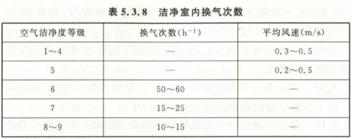
Note: 1 The number of air changes applies to clean rooms with a floor height of less than 4.0m.
2 When the number of indoor personnel is small and the heat source is low, the lower limit value should be adopted.
5.3.9 Air distribution in the air conditioning zone shall be determined based on the room temperature and humidity parameters and accuracy, the layout of the process equipment, the cleanliness level, wind speed, noise, and architectural decoration requirements, and shall comply with the following requirements:
1 The airflow distribution in the work area should be uniform.
2 The airflow velocity in the work area should meet the requirements of the production process and the health of the staff.
3 When the production area is a clean area, the airflow pattern should meet the cleanliness requirements.
5.3.10 The clean area and the surrounding environment should maintain a certain pressure difference, the static pressure difference between different levels of the clean area should not be less than 5Pa; the static pressure difference between the clean area and the non-clean area should not be less than 5Pa; The static pressure difference between the area and outdoor area should not be less than 10Pa.
5.3.11 The pressure difference air volume required to maintain different pressure differential values ​​in the clean area should be determined by the gap method or the number of air changes.
5.3.12 Air-conditioning air supply, return air and air exhaust system in the clean area shall be linked. When starting, the air blower shall be started first, and then the air blower and exhaust fan shall be started; the chain program shall be reversed when closed.
5.3.13 The selection and arrangement of air filters shall meet the following requirements:
1 The air purification treatment should use filters according to the air cleanliness level.
2 The actual air flow of the air filter should not exceed its rated air flow.
3 Medium and high efficiency air filters should be centrally located in the positive pressure section of the air conditioning system.
4 Sub-efficient and high-efficiency filters should be set at the end of the air conditioning system.
5 The ratio of resistance, efficiency, use air volume and rated air volume of the air filter in the same purification air-conditioning system should be similar.
5.3.14 Chemical plants with control requirements for chemical pollutants may adopt chemical filtration or other removal measures.
5.3.15 There should be sufficient absorption distance between the humidifier and the filter section of the air-conditioner, and the relative humidity of the air before the filter should not exceed 80% under humidifying conditions.
5.3.16 The air blower of a purified air-conditioning system should adopt frequency conversion measures. The blower can be selected according to the total air flow and the total resistance of the air conditioning system. The air filter resistance should be calculated according to the final resistance.
5.3.17 The electric heaters and electric humidifiers of the air-conditioning system shall be protected from wind and power failure protection, super-wet protection and grounding measures.
5.4 Smoke prevention
5.4.1 The design of the smoke control system shall comply with the relevant provisions of the current national standard "Code for the Fire Protection of Architectural Design" GB50016.
5.4.2 Mechanical exhaust system and ventilation and air conditioning system should be set separately. Smoke exhaust system should be combined with ventilation and air conditioning systems.
5.4.3 Mechanical smoke extraction system shall meet the following requirements:
1 The air-filling system should be set in the confined space, and the amount of supplemental air should not be less than 50% of the amount of smoke discharged, and the pressure difference between the inside and outside of the room evacuation door should not be greater than 30Pa.
2 In the event of a fire, the smoke outlets and exhaust fire dampers of the corresponding smoke partition should be manually and automatically opened, and non-fire power should be cut off at the same time. The exhaust fan and make-up fan should be opened after the exhaust port and the exhaust valve are fully opened.
5.5 Ducts and accessories
5.5.1 Ventilation and air conditioning system When the air duct is equipped with fire dampers, it shall comply with the relevant provisions of the current national standard "Code for the Fire Protection of Building Design" GB50016.
5.5.2 The selection of ducts and accessories shall comply with the following provisions:
1 The air ducts of non-corrosive ventilation systems and air-conditioning systems should be made of non-combustible materials.
2 The ducts for removing corrosive gases should be made of non-flammable or nonflammable materials that are resistant to corrosion and should be welded or welded.
3 organic exhaust pipe should use stainless steel, ammonia arc welding connection.
(4) Non-flammable or flame-retardant materials shall be used for attachments, insulation materials, noise-reducing materials, and anti-corrosion agents.
5 Accessories containing corrosive gas exhaust system should meet the requirements of corrosion protection.
5.5.3 Organic exhaust air ducts shall be provided with sweeping openings.
5.5.4 The silane gas exhaust pipe from the process equipment to the exhaust gas treatment tower shall be subjected to pressure test and vacuum test. The test method shall comply with the relevant provisions of the current national standard "Design Code for Industrial Metal Pipeline" GB50316.
5.5.5 When the noise of the air-conditioning system cannot meet the indoor noise control requirements, measures shall be taken to eliminate noise on the air supply and return air mains of the air-conditioning system. When the ventilation system noise cannot meet the indoor and outdoor noise control requirements, appropriate noise reduction and sound insulation measures shall be taken.
5.5.6 Before and after the air filter, pressure taps or pointer differential pressure gauges shall be provided. In the air-conditioning fresh air, return to the main air duct, should set the air volume measurement hole.
6 water supply and drainage
6.1 General provisions
6.1.1 The design of the water supply and drainage system should meet the requirements of production, living, fire control and environmental protection.
6.1.2 The design of the water supply and drainage system should select the comprehensive utilization scheme of water, and should be advanced technology, economical and reasonable, saving water and energy, and at the same time reduce the discharge of pollutants.
6.1.3 Sleeves should be provided when the water supply and drainage pipes pass through the walls or ceilings of the clean area. Sealing measures should be taken between the pipes and the casing.
6.1.4 The water supply and drainage pipes shall be provided with anti-freezing measures in a potentially frozen environment. When condensation may occur on the outer surface, dew condensation prevention measures shall be taken.
6.1.5 The dust-free material shall be used as the outermost layer of the heat insulation structure of the water supply and drainage pipe in the clean area.
6.2 General water supply and drainage
6.2.1 The water supply system should be set separately according to the different requirements of water quality, water pressure, and water temperature according to production, daily life, and fire protection.
6.2.2 The production and living water supply system should use the water pressure of the municipal water supply pipe network for direct water supply.
6.2.3 In the case of indirect water supply for production and domestic water supply systems, variable frequency speed control equipment should be used, and spare pumps should be provided. The standby pump's water supply capacity should not be less than the maximum one.
6.2.4 The drainage system of production wastewater shall be determined according to the nature of the wastewater, the quality of the water, the amount of water, and the process of wastewater treatment. Gravity flow shall be used to flow to the wastewater treatment station.
6.2.5 The dry pipe of production waste water should be set in the trench or under the interlayer, and the drainage pipe in the outdoor pipe trench in the cold area should adopt insulation and antifreeze measures.
6.2.6 Production Wastewater in Pipe Gutters The drain pipes should be protected against corrosion.
6.2.7 Measures should be taken to deal with accidental emergency drainage in the trench.
6.2.8 Production Wastewater The material of the drain pipe shall be selected according to the provisions of Appendix A according to the type, nature, concentration and temperature of the waste water.
6.2.9 Corrosive wastewater drain pipes laid in boring roofs Pipes or joints shall be provided with leak-proof measures.
6.2.10 The production and drainage of the process equipment in the clean area should adopt the take-over drainage, and the accidental floor drain should be set near the equipment. Drainage trunks should be equipped with a ventilation system.
6.2.11 The equipment, pipes, pipe racks and accessories that are not easy to accumulate dirt and are easy to clean should be used in the clean area.
6.2.12 Feedwater piping It is advisable to set up the metering device in the following positions:
1 Intake manifold of a production plant or building.
2 Inlet mains or make-up pipes for each water supply system.
3 Water refills for reservoirs or tanks (excluding fire-fighting reservoirs or tanks).
6.3 pure water
6.3.1 The location of the pure water station should meet the requirements of the overall layout of the process.
6.3.2 The pure water preparation process should be mature, economical, and easy to manage and operate reliably.
6.3.3 The design of the pure water system should meet the requirements for water quality at the point of use.
6.3.4 The material of the pure water pipeline should meet the water quality requirements of the production process. Polypropylene pipe, clean PVC pipe, polyvinylidene fluoride pipe, etc. should be selected. Pipe accessories and valves should be made of the same material as the pipe.
6.3.5 The pure water pipeline should adopt the circulating water supply method, and it should adopt the same-way arrangement. The amount of circulating water should be greater than 30% of the designed water consumption.
6.4 Wastewater treatment
6.4.1 The location of wastewater treatment facilities should meet the requirements of the overall layout of the process.
6.4.2 Wastewater treatment facilities should be determined according to the characteristics of wastewater discharged from the production process, such as the type, concentration, and volume of water discharged. The treated effluent quality should meet the current national and local emission standards.
6.4.3 Wastewater treatment should be based on the local environmental and socio-economic conditions, using mature, economical, easy to operate and reliable operation programs.
6.4.4 High-concentration fluor waste should be pretreated.
6.4.5 Soil monitoring points should be set around the wastewater treatment structures.
6.4.6 In cold areas, the wastewater treatment system should take antifreeze measures.
6.5 process cooling water
6.5.1 Process Circulation The water quality requirements of the cooling water system shall be determined according to the production process conditions.
6.5.2 Process Cycle The cooling water system should be set separately from other cooling water systems.
6.5.3 Process Cycles A closed system should be used for the cooling water system. For equipment with different requirements such as water temperature, water pressure, and operation, the circulating cooling water system should be set separately.
6.5.4 Process circulation The circulating water pump of the cooling water system should adopt variable frequency speed control. A standby pump should be set up. The water supply capacity of the standby pump should not be less than the water supply capacity of the largest one. Heat exchanger should set up a spare heat exchanger.
6.5.5 Process cycles The cooling system piping shall comply with the following provisions:
1 Filters, drain valves (drain outlets), exhaust valves (or exhaust outlets) and drain outlets should be provided.
2 The water distribution branch pipe shall take measures to balance the water quantity at each water use point.
3 The material of the process cooling water pipeline should be determined according to the water quality requirements of the production process
It is advisable to use stainless steel pipe or industrial water-repellent hard PVC pipe. Pipe Fittings and valves should be made of the same material as the pipe.
4 Between the insulating stainless steel pipe and the carbon steel hanger, a special insulating pipe card with an insulating block should be used.
6.5.6 Process circulation The cooling water system should be combined with the water quality conditions and reasonably set up a water quality stabilization treatment device.
6.6 Fire Water Supply and Fire Extinguisher Configuration
6.6.1 The silicon solar cell factory shall be equipped with indoor and outdoor fire hydrant water supply systems, and shall comply with the relevant provisions of the current national standard "Code for fire protection of architectural design" GB50016.
6.6.2 The silicon solar cell factory shall be equipped with a fire extinguisher, and shall comply with the relevant regulations of the current national standard "Configuration and Design of Building Fire Extinguisher" GB50140.
6.6.3 Dry powder fire extinguishers should not be used in the clean room of the factory.
6.6.4 The silicon solar cell factory building with an area of ​​more than 1500m2 or a total building area greater than 3000m2 shall be equipped with an automatic sprinkler system and shall comply with the relevant provisions of the current national standard "Specifications for Automatic Sprinkling System Design" GB50084.
6.6.5 When setting up an automatic sprinkler system, if there is flammable material in the workshop where the headroom is greater than 800 mm or the total height is greater than 1800 mm, sprinklers shall be provided.
6.6.6 The pre-action automatic sprinkler system should be used in the clean area of ​​the plant and the place where the system is forbidden to accidentally spray or leak the pipe.
7 Gas Power and Chemical Transportation
7.1 Gas Station Room
7.1.1 The location of the gas station room shall meet the rationality and safety requirements of the process layout and may be combined with the freezing station room.
7.1.2 The compressed air and vacuum used in the silicon solar cell plant should meet the requirements of the process.
7.1.3 Selection of air compressors and vacuum pumps shall be determined after technical and economic comparisons based on factors such as gas usage and quality, and should be set aside.
7.1.4 Air compressors should use oil-free compressors.
7.1.5 The oil-lubricated vacuum pump should be equipped with a degreasing device. The degassed exhaust gas should be discharged separately to the outside, and the minimum distance of the discharge outlet from the new wind population should not be less than 6m.
7.1.6 The compressed air pipeline should adopt galvanized steel pipe or stainless steel pipe, and the valve should adopt ball valve. The vacuum pipeline should adopt galvanized steel pipe, stainless steel pipe or water-hard PVC pipe, and the valve should adopt butterfly valve or ball valve. Gas system valves and accessories should be consistent with the pipe material.
7.1.7 The design of gas station buildings and pipelines shall comply with the relevant provisions of the current national standard "Design Specification for Compressed Air Station" GBSOO29.
7.2 Special Gas Systems
7.2.1 Special gases such as silane, ammonia, and carbon tetrachloride used in silicon solar cell plants should be stored in purchased liquid gas cylinders or gaseous gas cylinders, and should be distributed in pipelines.
7.2.2 The amount of special gas stored in the storage and distribution of special gases in the silicon solar cell plant should not exceed the requirement for 24 hours.
7.2.3 The distribution of special gas systems shall be distributed within the valve box and shall not be branched directly on the piping.
7.2.4 Special gas systems In addition to valves in special gas cabinets, valve boxes, and equipment, no valves may be installed in other parts of the system.
7.2.5 The special gas distribution system shall be set up as specified in Appendix B. The setting of a flammable or toxic special gas distribution system shall also comply with the following provisions:
1 Gas cylinders should be placed in special gas cabinets with continuous mechanical ventilation. The gas cabinets should be equipped with gas detection alarms and automatically cut off the output gas. Gas detection alarms should be linked to mechanical ventilators.
2 In areas where special gas distribution systems may leak, and where there are valves, fittings, etc., mechanical exhaust devices and gas detection alarms shall be provided; when toxic or combustible gases are detected, alarms shall be made, and gas supply and start-up shall be correspondingly Mechanical exhaust.
3 The emergency exhaust fan, detection alarm, shut-off valve, etc. shall be provided with standby power.
4 When a special gas distribution system is used for multiple production equipment, multi-valve valve boxes should be set up.
7.2.6 The special gas distribution system shall be equipped with a purge system. The purge system shall meet the following requirements:
1 emergency cut-off device should be configured.
2 Anti-backflow device should be set.
3 Manual isolation valve should be set.
4 The purge gas source shall be supplied with high-purity nitrogen gas by special cylinders or cylinder groups. Purge systems for incompatible special gases shall not share purge cylinders.
7.2.7 The silane gas pipeline should adopt double casing. The outer casing can use OCr18Nig stainless steel pickling pipe, and the inner pipe can use 00Cr17Ni12MoZTi stainless steel inner wall electric polishing pipe. Diaphragm valves should be used for valves.
7.2.8 Ammonia tube can be 00Cr17Ni12MoZTi stainless steel inner wall electropolishing tube.
7.2.9 Special gas pipelines shall be connected to the openings of valves and equipments except for the requirement of flanges or threaded connections. They shall be hydrogen arc welded.
7.2.10 Combustible special gas pipelines should be laid overhead.
7.2.11 Combustible and toxic special gas pipelines shall not pass through rooms that do not use the gas.
7.3 Bulk Gas Supply
7.3.1 The gas supply method for the bulk gas in the silicon solar cell plant can adopt the following methods:
1 Regional centralized pipe network supply.
2Liquid gas storage tanks, carburetors and gas transmission pipelines are installed in the plant.
3 Steam facilities are located in or near the plant area, purified and then transported to the point of use via pipelines.
4 In the factory, set up a cylinder bank and a gas pipeline.
7.3.2 Oxygen pipelines in the workshop should be equipped with discharge pipes in place. Discharge pipe should be out of the wall, and should be connected to the open area above 4m above the open, non-fire place, the dissemination of the pipe should take measures to prevent rain, lightning, and foreign objects invade.
7.3.3 Gas pipeline control valves, gas filters, pressure regulators, pressure gauges, flow meters, and on-line analyzers that are connected to the plant should be centrally located.
7.3.4 Safety measures for oxygen pipelines shall comply with the following provisions:
1 The pipeline and valve accessories should be strictly degreasing.
2 The pipeline should take anti-static grounding measures.
3 The sealing material used for oxygen pipe connection is strictly prohibited to use grease-containing materials.
7.3.5 Cylinders should be centrally located outside the clean area. When the amount of gas used is less than 1 bottle a day, the gas bottle may be set in a clean area but measures should be taken not to accumulate dust and be easy to clean.
7.3.6 Gas pipelines should be polished with degreased 0Crl8Nig stainless steel tubes. The valve should adopt ball valve or bellows valve. The material of the valve and accessories of the gas pipe should be consistent with the pipe.
7.3.7 Gas pipeline connections shall comply with the following provisions:
1 Pipe connection should be hydrogen arc welding.
2 The connection form of the pipeline and the equipment should meet the connection requirements of the equipment, and it should be connected with a flange or double ferrules. The sealing material should be metal pads or PTFE mats. When using a hose connection, metal hoses should be used.
7.4 Cold and Heat Sources
7.4.1 The selection of cold and heat sources for silicon solar cell plants shall be determined by comprehensive demonstration according to factors such as production scale, cold and heat load, meteorological conditions in the region, energy structure and policies, price and environmental protection. In addition, priority should be given to the existing cooling and heating systems around the factory.
7.4.2生产工艺ã€é‡‡æš–ã€ç©ºè°ƒç‰ç³»ç»Ÿæ‰€éœ€çš„冷çƒæºç«™æˆ¿ï¼Œå®œé›†ä¸è®¾ç½®ï¼Œå¹¶å®œè®¾ç½®åœ¨è´Ÿè·ä¸å¿ƒé™„近。
7.4.3冷水机组的选择应符åˆä¸‹åˆ—规定:
1应符åˆæ»¡è´Ÿè·è¿è¡Œå’Œéƒ¨åˆ†è´Ÿè·è¿è¡Œçš„调节è¦æ±‚,ä¸å®œå°‘于2å°ã€‚
2è´Ÿè·å°ä»…设1å°å†·æ°´æœºç»„时,应选调节性能优良的机型。
7.4.4选用电动压缩å¼å†·æ°´æœºæ—¶ï¼Œå…¶åˆ¶å†·å‰‚应符åˆå›½å®¶çŽ°è¡Œæœ‰å…³çŽ¯ä¿çš„è¦æ±‚。
7.4.5锅炉房设计应符åˆçŽ°è¡Œå›½å®¶æ ‡å‡†ã€Šé”…炉房设计规范》GB50041的有关规定。
7.4.6冷çƒæ°´ç³»ç»Ÿçš„设计应符åˆä¸‹åˆ—规定:
1宜采用é—å¼å¾ªçŽ¯ç³»ç»Ÿã€‚
2水系统的定压和膨胀宜采用高ä½è†¨èƒ€æ°´ç®±çš„æ–¹å¼ã€‚
3åº”æ ¹æ®å½“地水质情况采å–过滤ã€é™¤åž¢ã€æ€èŒã€çè—»ç‰æ°´å¤„ç†æŽªæ–½ã€‚
4åº”æ ¹æ®è®¡ç®—采å–水力平衡措施。
5制冷ã€åˆ¶çƒè®¾å¤‡ã€ç®¡é“åŠå…¶é™„件ã€é˜€é—¨ç‰å‡åº”ä¿å†·æˆ–ä¿æ¸©ã€‚
ä¿å†·ã€ä¿æ¸©çš„管é“和支架之间,管é“穿墙ã€ç©¿æ¥¼æ¿å¤„应采å–防æ¢â€œå†·æ¡¥â€ã€â€œçƒæ¡¥â€çš„措施。
6ä¿å†·ã€ä¿æ¸©æ料的主è¦æŠ€æœ¯æ€§èƒ½ï¼Œåº”符åˆçŽ°è¡Œå›½å®¶æ ‡å‡†ã€Šè®¾å¤‡åŠç®¡é“ç»çƒè®¾è®¡å¯¼åˆ™ã€‹GBï¼T8175的有关规定,并宜选用导çƒç³»æ•°å°ã€å¸æ°´çŽ‡ä½Žã€æ¹¿é˜»å› å大ã€å¯†åº¦å°çš„ä¸ç‡ƒæˆ–难燃的ä¿å†·ã€ä¿æ¸©æ料。
7冷çƒæ°´ç³»ç»Ÿçš„水泵应设置备用泵。
7.5化å¦å“输é€
7.5.1ç¡…å¤ªé˜³èƒ½ç”µæ± åŽ‚æˆ¿ä½¿ç”¨çš„é…¸ã€ç¢±ã€æœ‰æœºæº¶å‰‚,应符åˆç”Ÿäº§å·¥è‰ºçš„è¦æ±‚,其储å˜ã€è¾“é€æ–¹å¼åº”æ ¹æ®ç”Ÿäº§è§„模ã€å·¥è‰ºè¦æ±‚确定。
7.5.2规模化连ç»ç”Ÿäº§çš„ç¡…å¤ªé˜³èƒ½ç”µæ± å·¥åŽ‚ï¼Œå®œè®¾ç½®åŒ–å¦å“集ä¸ä¾›åº”系统。
7.5.3ç¡…å¤ªé˜³èƒ½ç”µæ± åŽ‚æˆ¿å†…çš„åŒ–å¦å“库房或ç½åŒºè®¾è®¡ï¼Œåº”符åˆçŽ°è¡Œå›½å®¶æ ‡å‡†ã€Šå»ºç‘设计防ç«è§„范》GB50016的有关规定。甲乙类液体化å¦å“的轻便容器å˜æ”¾åœ¨å®¤å¤–时,应设置防晒棚或设置冷å´è®¾æ–½ã€‚
7.5.4ç¡…å¤ªé˜³èƒ½ç”µæ± åŽ‚æˆ¿åŒ–å¦å“库ã€ä¸é—´åº“ã€åˆ†é…é—´ä¸å˜æ”¾çš„化å¦å“有å¯èƒ½æ•£å‘有害气体或爆炸å±é™©æ°”体时,应设置机械通风。
7.5.5化å¦å“库ã€ä¸é—´åº“ã€åˆ†é…间,宜设置集液地沟或集液å‘。
7.5.6化å¦å“库ã€ä¸é—´åº“ã€åˆ†é…间以åŠä½¿ç”¨ç‚¹ï¼Œåº”设置紧急淋浴洗眼器。
7.5.7化å¦å“输é€ä¸Žåˆ†é…系统应设置检测å–æ ·å£ã€äº‹æ•…排放å£åŠæ³„æ¼æŽ¢æµ‹æŠ¥è¦ç³»ç»Ÿï¼Œç®¡é“宜采用åŒå±‚管。
7.5.8化å¦å“集ä¸è¾“é€ç”¨æ³µåº”设置备用泵åŠäº‹æ•…应急桶,化å¦å“输é€ç®¡é“在分é…和使用处应设置手动切æ–阀。
7.5.9化å¦å“输é€åŽ‹åŠ›åº”符åˆç”Ÿäº§ä½¿ç”¨çš„è¦æ±‚。化å¦å“输é€ç”¨å¡‘料管é“的设计应符åˆçƒèƒ€å†·ç¼©çš„è¦æ±‚。
7.5.10化å¦å“输é€è®¾å¤‡åŠç®¡æç®¡ä»¶çš„é€‰ç”¨ï¼Œåº”æ ¹æ®åŒ–å¦å“的物ç†åŒ–å¦æ€§è´¨ç¡®å®šï¼Œå¹¶åº”ç¡®ä¿åŒ–å¦å“在输é€è¿‡ç¨‹ä¸ä¸å¢žåŠ 金属离åçš„å«é‡ã€‚
7.5.11化å¦å“管路用阀门ã€ç®¡ä»¶ç‰çš„æ质应与使用管é“æ质一致。
7.5.12化å¦å“管é“与管é“支架接触的地方,应采å–防æ¢ç®¡è·¯æ‘©æ“¦æŸå的措施。
8电气设计
8.1供电系统
8.1.1ç¡…å¤ªé˜³èƒ½ç”µæ± åŽ‚æˆ¿çš„ä¾›ç”µç³»ç»Ÿè®¾è®¡é™¤åº”ç¬¦åˆç”Ÿäº§å·¥è‰ºè¦æ±‚外,还应符åˆçŽ°è¡Œå›½å®¶æ ‡å‡†ã€Šä¾›é…电系统设计规范》GB50052的有关规定。
8.1.2生产用主è¦å·¥è‰ºè®¾å¤‡ï¼Œå®œç”±ä¸“用å˜åŽ‹å™¨æˆ–专用低压馈电线路供电。
8.1.3对电æºè¿žç»æ€§æœ‰ç‰¹æ®Šè¦æ±‚的设备åŠä»ªè¡¨ï¼Œåº”设置ä¸é—´æ–电æºï¼›å¯¹ç”µæºå¯é 性有特殊è¦æ±‚的排风ç‰è®¾å¤‡ï¼Œå®œè®¾ç½®å¤‡ç”¨ç”µæºã€‚
8.1.4消防负è·çš„ä¾›é…电设计,应符åˆçŽ°è¡Œå›½å®¶æ ‡å‡†ã€Šå»ºç‘设计防ç«è§„范》GB50016的有关规定。
8.1.5厂房低压é…电电压ç‰çº§åº”符åˆç”Ÿäº§å·¥è‰ºç”¨ç”µè¦æ±‚,宜采用380Vï¼220V。系统接地型å¼å®œé‡‡ç”¨TN-5或TN-CS系统。
8.1.6å˜ç”µæ‰€å®œä»¥è‡ªç„¶é€šé£Žä¸ºä¸»ï¼Œå½“自然通风ä¸èƒ½æ»¡è¶³çŽ¯å¢ƒæ¸©åº¦è¦æ±‚时,应设置机械通风或空调系统。
8.1.7å˜åŽ‹å™¨ä½ŽåŽ‹ä¾§åº”è®¾ç½®ä½ŽåŽ‹æ— åŠŸè¡¥å¿æŸœï¼Œæ— 功补å¿æŸœå®œå…·å¤‡è‡ªåŠ¨è¿‡é›¶æŠ•åˆ‡ã€åˆ†ç›¸è¡¥å¿ç‰åŠŸèƒ½ï¼Œå¹¶åº”åŠ è£…é€‚é‡çš„电抗器。
8.1.8对于è°æ³¢ç‰¹åˆ«ä¸¥é‡çš„设备,应在设备处设置相应的è°æ³¢å¤„ç†è£…置或预留消除è°æ³¢è£…置的接å£ã€‚
8.2电力照明
8.2.1ç¡…å¤ªé˜³èƒ½ç”µæ± åŽ‚æˆ¿çš„é…电系统设计应符åˆç”Ÿäº§å·¥è‰ºçš„è¦æ±‚。
8.2.2有净化è¦æ±‚的生产车间内,宜选择ä¸æ˜“积尘ã€ä¾¿äºŽæ“¦æ‹çš„é…电设备。
8.2.3技术夹层内的电气é…管宜采用金属管。æ´å‡€åŒºçš„电气管线宜暗敷,穿线导管应采用ä¸ç‡ƒæ料。
8.2.4æ´å‡€åŒºçš„电气管线管å£åŠå®‰è£…于墙上的电器设备与墙体接ç¼å¤„,应采å–密å°æŽªæ–½ã€‚
8.2.5ç¡…å¤ªé˜³èƒ½ç”µæ± åŽ‚æˆ¿ä¸»è¦ç”Ÿäº§ç”¨æˆ¿é—´ä¸€èˆ¬ç…§æ˜Žçš„照度值,ä¸å®œä½ŽäºŽ300lx,辅助用房一般照明的照度值,应符åˆçŽ°è¡Œå›½å®¶æ ‡å‡†ã€Šå»ºç‘ç…§æ˜Žè®¾è®¡æ ‡å‡†ã€‹GB50034的有关规定。
8.2.6ç¡…å¤ªé˜³èƒ½ç”µæ± åŽ‚æˆ¿ä½œä¸šåŒºåŸŸå†…ä¸€èˆ¬ç…§æ˜Žçš„ç…§åº¦å‡åŒ€åº¦ï¼Œä¸åº”å°äºŽ0.7。
8.2.7备用照明的设置应符åˆä¸‹åˆ—规定:
1æ´å‡€åŒºå†…应设置备用照明。
2备用照明宜作为æ£å¸¸ç…§æ˜Žçš„一部分,且ä¸åº”低于该场所一般照明照度值的10%。
8.2.8厂房内应设置供人员ç–散用的应急照明。在安全出人å£ã€ç–散通é“或ç–散通é“è½¬è§’å¤„ï¼Œåº”æŒ‰çŽ°è¡Œå›½å®¶æ ‡å‡†ã€Šå»ºç‘设计防ç«è§„范》GB50016的有关规定设置ç–æ•£æ ‡å¿—ã€‚
8.2.9厂房技术夹层内宜设置检修照明。
8.2.10æ´å‡€åŒºå†…一般照明用ç¯å…·ï¼Œå®œé‡‡ç”¨å¸é¡¶æ˜Žè£…ã€ä¸æ˜“集尘ã€ä¾¿äºŽæ¸…æ´çš„æ´å‡€èŠ‚能ç¯å…·ã€‚采用嵌人å¼ç¯å…·æ—¶ï¼Œå®‰è£…ç¼éš™åº”采å–密å°æŽªæ–½ã€‚
8.3ä¿¡æ¯ä¸Žè‡ªæŽ§
8.3.1厂房内通信设施的设置,应符åˆä¸‹åˆ—规定:
1应设置便于æ´å‡€åŒºå†…外è”系的è¯éŸ³é€šä¿¡è£…置。
2å¯è®¾ç½®æ•°æ®é€šä¿¡è£…置。
3系统布线宜采用综åˆå¸ƒçº¿ç³»ç»Ÿã€‚
4ä¼ é€’çª—ä¸¤ä¾§å®œè®¾ç½®å¯¹è®²è£…ç½®ã€‚
5通信机房ã€é…线间ä¸å®œè®¾ç½®åœ¨æ´å‡€åŒºå†…。
8.3.2厂房应设置ç«ç¾è‡ªåŠ¨æŠ¥è¦ç³»ç»Ÿï¼Œå…¶é˜²æŠ¤å¯¹è±¡çš„ç‰çº§ä¸åº”低于二级。
8.3.3厂房应设置ç«ç¾è‡ªåŠ¨æŠ¥è¦åŠæ¶ˆé˜²è”动控制,ç«ç¾è‡ªåŠ¨æŠ¥è¦åŠæ¶ˆé˜²è”动控制åŠæ˜¾ç¤ºåŠŸèƒ½ï¼Œåº”符åˆçŽ°è¡Œå›½å®¶æ ‡å‡†ã€Šç«ç¾è‡ªåŠ¨æŠ¥è¦ç³»ç»Ÿè®¾è®¡è§„范》GB50116的有关规定。
8.3.4消防控制室ä¸åº”设置在æ´å‡€åŒºå†…。
8.3.5下列区域应设置ç«ç¾æŽ¢æµ‹å™¨ï¼š
1æ´å‡€ç”Ÿäº§åŒºã€‚
2技术夹层。
3å˜é…电室。
4空调机房。
5气体站房ã€å†·å†»ç«™æˆ¿ã€‚
6特ç§æ°”体间。
8.3.6ç¡…å¤ªé˜³èƒ½ç”µæ± åŽ‚æˆ¿æ´å‡€åŒºç«ç¾æŠ¥è¦ä¿¡å·åº”è¿›è¡Œæ ¸å®žï¼Œç¡®è®¤ç«ç¾åŽï¼Œåº”在消防控制室对下列å„项进行è”动控制:
1应关é—有关部ä½çš„电动防ç«é˜€ï¼Œå¹¶åº”åœæ¢ç›¸åº”的净化空调系统的循环风机ã€æŽ’风机和新风机,åŒæ—¶åº”接收其å馈信å·ã€‚
2应å¯åŠ¨æŽ’烟风机,并应接收其å馈信å·ã€‚
3应å¯åŠ¨å£°å…‰æŠ¥è¦å™¨ã€‚
4应å¯åŠ¨ç«ç¾åº”急广æ’,并应进行人工或自动ç«è¦å¹¿æ’。
5在消防控制室或低压é…电室,应切æ–有关部ä½çš„éžæ¶ˆé˜²ç”µæºã€‚
8.3.7下列场所应设置气体报è¦è£…置:
1易燃ã€æ˜“爆ã€æœ‰æ¯’气体的使用场所åŠæ°”体管é“人å£å®¤çš„管é“阀门或接头ç‰æ˜“泄æ¼å¤„。
2易燃ã€æ˜“爆ã€æœ‰æ¯’气体的储å˜ã€åˆ†é…场所。
3易燃ã€æ˜“爆ã€æœ‰æ¯’气体气瓶柜和分é…阀门箱内。
8.3.8气体报è¦ç³»ç»Ÿåœ¨çŽ°åœºåº”设置泄æ¼å£°å…‰æŠ¥è¦ï¼Œæ³„æ¼å£°å…‰æŠ¥è¦åº”有别于现场的ç«ç¾æŠ¥è¦ã€‚
8.3.9气体报è¦çš„è”动控制,应符åˆä¸‹åˆ—规定:
1应自动å¯åŠ¨ç›¸åº”的事故排风装置,并应接å—å馈信å·ã€‚
2应自动关é—相关部ä½çš„进气气体切æ–阀,并应接å—å馈信å·ã€‚
3应å¯åŠ¨æ³„æ¼çŽ°åœºçš„声光报è¦è£…置。
8.3.10气体报è¦åŠæŽ§åˆ¶ç³»ç»Ÿçš„供电å¯é è¦æ±‚,ä¸åº”低于åŒæœŸå·¥ç¨‹çš„ç«ç¾æŠ¥è¦ç³»ç»Ÿä¾›ç”µå¯é è¦æ±‚。
8.3.11ç¡…å¤ªé˜³èƒ½ç”µæ± åŽ‚æˆ¿å®œè®¾ç½®åº”æ€¥å¹¿æ’。æ´å‡€åŒºå†…扬声器的选择应ä¿è¯ä¸å½±å“æ´å‡€åŒºçš„æ´å‡€ç‰çº§ã€‚
8.3.12下列系统宜设置自动监控系统:
1净化空调系统。
2特ç§æ°”体系统。
3化å¦å“输é€ç³»ç»Ÿã€‚
4纯水和废水处ç†ç³»ç»Ÿã€‚
8.3.13å‡€åŒ–ç©ºè°ƒç³»ç»Ÿé‡‡ç”¨ç”µåŠ çƒå™¨æ—¶ï¼Œåº”采å–æ— é£Žã€è¶…温ä¿æŠ¤æŽªæ–½ï¼›é‡‡ç”¨ç”µåŠ 湿器时,应采å–æ— æ°´ä¿æŠ¤æŽªæ–½ã€‚在寒冷地区,新风系统应采å–防冻ä¿æŠ¤æŽªæ–½ã€‚
8.4接地
8.4.1厂区的防雷接地系统设计,应符åˆçŽ°è¡Œå›½å®¶æ ‡å‡†ã€Šå»ºç‘物防雷设计规范》GBSOO57的有关规定。
8.4.2下列设备ã€æµåŠ¨æ¶²ä½“或气体管é“,应采å–防é™ç”µæŽ¥åœ°æŽªæ–½ï¼š
1氧气管é“。
2氨气管é“。
3硅烷管é“。
4排除有燃烧或爆炸å±é™©ç‰©è´¨çš„设备和风管。
5净化空调系统风管。
6其他生产工艺è¦æ±‚的设备或管é“。
8.4.3电åä¿¡æ¯ç³»ç»Ÿç”µç¼†è¿›å‡ºå»ºç‘物时,应设置适é…çš„ä¿¡å·æµªæ¶Œä¿æŠ¤å™¨ã€‚
8.4.4有高频接地è¦æ±‚的工艺设备宜å•ç‹¬è®¾ç½®æŽ¥åœ°ç³»ç»Ÿï¼Œå¹¶åº”与防雷接地系统的接地体ä¿æŒè‡³å°‘20mçš„é—´è·ã€‚
8.4.5厂房的防雷接地ã€é˜²é™ç”µæŽ¥åœ°ã€ç”µåä¿¡æ¯ç³»ç»ŸæŽ¥åœ°ç‰ï¼Œå®œé‡‡ç”¨å…±ç”¨æŽ¥åœ°æ–¹å¼ï¼ŒæŽ¥åœ°ç”µé˜»å€¼ä¸åº”大于1Ω,并应实施ç‰ç”µä½è”结措施。
9节能与资æºåˆ©ç”¨
9.1建ç‘节能
9.1.1建ç‘总平é¢çš„布置和设计,宜利用冬å£æ—¥ç…§ï¼Œå¹¶å®œé¿å¼€å†¬å£ä¸»å¯¼é£Žå‘,åŒæ—¶å®œåˆ©ç”¨å¤å£è‡ªç„¶é€šé£Žã€‚建ç‘主æœå‘宜选择当地最佳æœå‘或接近最佳æœå‘。
9.1.2ç¡…å¤ªé˜³èƒ½ç”µæ± åŽ‚æˆ¿çš„å»ºç‘外墙æ料宜采用国家推èçš„ä¿æ¸©ã€èŠ‚能型æ料,严ç¦ä½¿ç”¨æ·˜æ±°äº§å“。
9.1.3厂房屋é¢åº”采å–ä¿æ¸©ã€éš”çƒæŽªæ–½ã€‚有æ¡ä»¶çš„地方,å¯åˆ©ç”¨å±‹é¢å®‰è£…太阳能集çƒå™¨æˆ–å¤ªé˜³ç”µæ± ç»„ä»¶ã€‚
9.1.4厂房外窗åŠé€æ˜Žå¹•å¢™åº”有良好的气密性。
9.2空调系统节能
9.2.1空气调节系统应åˆç†åˆ©ç”¨å·¥è‰ºäº§ç”Ÿçš„废çƒã€‚
9.2.2ç©ºæ°”è°ƒèŠ‚ç³»ç»Ÿåº”æ ¹æ®ç”Ÿäº§ç‰¹ç‚¹å’Œç³»ç»Ÿçš„实际装设情况进行监测和控制,监测和控制内容应包括å‚数检测ã€å‚数与设备状æ€æ˜¾ç¤ºã€è‡ªåŠ¨è°ƒèŠ‚与控制ã€å·¥å†µè‡ªåŠ¨è½¬æ¢ã€èƒ½é‡è®¡é‡ã€åŠŸèƒ½è¿žé”控制,以åŠä¸å¤®ç›‘控与管ç†ç‰ã€‚
9.2.3空调系统的风管ç»çƒå±‚,应采用ä¸ç‡ƒæˆ–难燃æ料,且ç»çƒå±‚çš„çƒé˜»ä¸åº”å°äºŽ0.74m2·Kï¼W。ç»çƒå±‚外应设置隔气层和ä¿æŠ¤å±‚。
9.2.4空气调节系统所用的çƒæ°´ç®¡å’Œå†·æ°´ç®¡çš„ç»çƒåŽšåº¦ï¼Œåº”æŒ‰çŽ°è¡Œå›½å®¶æ ‡å‡†ã€Šè®¾å¤‡åŠç®¡é“ç»çƒè®¾è®¡å¯¼åˆ™ã€‹GBï¼T8175çš„ç»æµŽåŽšåº¦å’Œé˜²è¡¨é¢ç»“éœ²åŽšåº¦çš„æ–¹æ³•è®¡ç®—ï¼Œç¡…å¤ªé˜³èƒ½ç”µæ± åŽ‚æˆ¿å»ºç‘物内的空气调节冷çƒæ°´ç®¡äº¦å¯æŒ‰é™„录Cçš„è¦æ±‚选用。
9.3冷çƒæºç³»ç»ŸèŠ‚能
9.3.1冷çƒæºçš„选择应充分利用太阳能ã€åœ°çƒèƒ½ã€ç©ºæ°”çƒæ³µã€åœ°ä¸‹å«æ°´å±‚蓄能以åŠå…¶ä»–自然冷ã€çƒæºç‰å¤©ç„¶å†·ã€çƒæºã€‚
9.3.2在åŒæ—¶éœ€è¦ä¾›å†·å’Œä¾›çƒçš„å·¥å†µä¸‹ï¼Œå†·æ°´æœºç»„å®œæ ¹æ®è´Ÿè·è¦æ±‚选用çƒå›žæ”¶æœºç»„,并宜采用控制çƒæ°´å›žæ°´æ¸©åº¦çš„æ–¹å¼æŽ§åˆ¶çƒé‡ã€‚
9.3.3冷水机组的冷水供ã€å›žæ°´æ¸©å·®ä¸åº”å°äºŽ5℃,在技术å¯é ã€ç»æµŽåˆç†çš„å‰æä¸‹ï¼Œå®œåŠ å¤§å†·æ°´ä¾›ã€å›žæ°´æ¸©å·®ã€‚在满足工艺åŠç©ºè°ƒç”¨å†·çš„å‰æ下,å¯æ高冷水机组出水温度。采用çƒå›žæ”¶æœºç»„时,宜采用全çƒå›žæ”¶æ–¹å¼ã€‚
9.3.4水冷å¼å†·æ°´æœºç»„的冷å´æ°´åº”循环使用。冷å´æ°´çš„çƒé‡å®œå›žæ”¶åˆ©ç”¨ã€‚
9.3.5过渡å£èŠ‚或冬å£éœ€ç”¨å°‘é‡çš„供冷负è·æ—¶ï¼Œå¯åˆ©ç”¨å†·å´å¡”作为冷æºè®¾å¤‡ã€‚
9.4设备节能
9.4.1动力设备应选用高效率ã€ä½Žèƒ½è€—的机型,ä¸åº”采用淘汰产å“。
9.4.2水泵宜采用å˜é¢‘调速控制。
9.4.3冷水机组宜采用å˜é€Ÿç¦»å¿ƒå†·æ°´æœºç»„。
9.4.4冷水机组的能效比ä¸åº”ä½ŽäºŽçŽ°è¡Œå›½å®¶æ ‡å‡†ã€Šå†·æ°´æœºç»„èƒ½æ•ˆé™å®šå€¼åŠèƒ½æºæ•ˆçŽ‡ç‰çº§ã€‹GB19577的规定值,并应选用能效比高的设备。
9.4.5燃油燃气锅炉应选用带比例调节燃烧器的全自动锅炉,且æ¯å°é”…炉宜独立设置烟囱,烟囱的高度应符åˆçŽ°è¡Œå›½å®¶æ ‡å‡†ã€Šé”…ç‚‰å¤§æ°”æ±¡æŸ“ç‰©æŽ’æ”¾æ ‡å‡†ã€‹GB13271的有关规定。
9.4.6çƒæºè®¾å¤‡å°æ•°å’Œå®¹é‡åº”æ ¹æ®å…¨å¹´çƒè´Ÿè·å·¥å†µåˆç†é€‰æ‹©ï¼Œå¹¶åº”ä¿è¯è®¾å¤‡åœ¨é«˜ã€ä½Žçƒè´Ÿè·å·¥å†µä¸‹å‡èƒ½å®‰å…¨ã€é«˜æ•ˆè¿è¡Œã€‚
9.4.7å¼€å¼å†·å´æ°´ç³»ç»Ÿçš„循环利用率应达到95%以上,开å¼æœºæ¢°é€šé£Žå†·å´å¡”的飘水率应å°äºŽè¿›å¡”总水é‡çš„0.01%。
9.5电气节能
9.5.1å˜ç”µæ‰€å®œè®¾ç½®èƒ½æºç®¡ç†ç³»ç»Ÿã€‚功率大于或ç‰äºŽ50kw的用电装置,宜å•ç‹¬é…置电æµè¡¨ã€æœ‰åŠŸç”µèƒ½è¡¨ç‰è®¡é‡è£…置。
9.5.2电气系统设计应采用符åˆå›½å®¶çŽ°è¡Œæœ‰å…³æ ‡å‡†çš„效率高ã€èƒ½è€—低ã€æ€§èƒ½å…ˆè¿›çš„电气产å“,ä¸åº”采用淘汰产å“。
9.5.3照明ç¯å…·é•‡æµå™¨çš„选择,应符åˆçŽ°è¡Œå›½å®¶æ ‡å‡†ã€Šå»ºç‘ç…§æ˜Žè®¾è®¡æ ‡å‡†ã€‹GB50034的有关规定,且宜采用电å镇æµå™¨æˆ–节能型电感镇æµå™¨ã€‚
9.5.4采用电感镇æµå™¨çš„气体放电ç¯ï¼Œå®œåœ¨çº¿è·¯æˆ–ç¯å…·å†…设置电容补å¿ï¼ŒåŠŸçŽ‡å› æ•°ä¸åº”低于0.9。
9.5.5厂区é“路照明的路ç¯ï¼Œå®œé‡‡ç”¨å…‰ç”µå’Œæ—¶é—´æŽ§åˆ¶ï¼Œå¹¶åº”采用节能ç¯å…·ã€‚
9.5.6ç¡…å¤ªé˜³èƒ½ç”µæ± åŽ‚æˆ¿å˜åŽ‹å™¨å°æ•°å’Œå®¹é‡çš„选择与é…ç½®ï¼Œåº”æ ¹æ®ç”Ÿäº§å·¥è‰ºåŠå…¶é…套辅助设施ã€å…¬ç”¨åŠ¨åŠ›è®¾æ–½ç‰çš„用电负è·ç‰¹ç‚¹å’Œå˜åŒ–状况确定,并应符åˆä¸‹åˆ—规定:
1应选择低æŸè€—ã€ä½Žå™ªå£°çš„节能型å˜åŽ‹å™¨ã€‚
2å˜åŽ‹å™¨çš„容é‡å®œæ ¹æ®å˜åŽ‹å™¨èŠ‚能ã€èŠ‚电和裕é‡è¿›è¡Œé€‰æ‹©ã€‚
3多å°å˜åŽ‹å™¨ä¹‹é—´å®œè®¾ç½®ä½ŽåŽ‹è”络。
9.6资æºåˆ©ç”¨
9.6.1下列水宜回收或收集利用:
1空调冷å‡æ°´ã€‚
2蒸汽å‡ç»“水。
3纯水系统的å渗é€æµ“水。
4屋é¢é›¨æ°´ã€‚
5废水处ç†åŽçš„排放水。
9.6.2çº¯æ°´ç³»ç»ŸåŠ çƒçš„çƒæºï¼Œå®œåˆ©ç”¨å›žæ”¶çƒæºã€‚ .
9.6.3工艺废水处ç†åº”éµå¾ªèŠ‚水优先ã€åˆ†è´¨å¤„ç†ã€ä¼˜å…ˆå›žç”¨çš„原则。废水回用率ä¸å®œä½ŽäºŽ50%。
Gate valve is a gate opening and closing gate, the direction of movement of the gate and fluid perpendicular to the gate valve can only be fully open and fully closed, can not be adjusted and throttling. Valve through the valve seat and gate contact seal, usually sealing surface will be surfacing metal materials to increase the wear resistance, such as surfacing 1Cr13, STL6, stainless steel and so on. Gate valve is divided into rigid gate valve and flexible gate valve.
Material: Cast Iron, Ductile Iron,Carbon steel,Stainless steel
Type: Flanged, Screwed, Grooved
Standard: Class 125 to Class 250, or PN16 to PN25.
Size: 2" to 14"
Application: Pipelines with Water, Oil, Gas.
All other details or types, please send free requirments.
1.BS5150

2. DIN3352

Gate Valves,Flange Gate Valve,Resilent Seated Gate Valve,Grooved Gate Valve
HEBEI ZIFENG NEW ENERGY TECHNOLOGY CO.,LTD. , https://www.zifengpipeline.com