1 Overview
Qilu Petrochemical Thermal Power Plant 2# generator set is manufactured by SAIC, model: CC50—90—42—15—1, cylinder material ZG20CrMo, as shown in Figure 1. Operating temperature 535 ° C, since May 1, 1988. In the major overhaul in March 2008, it was found by metallographic examination that there was a crack of nearly 50mm on the joint surface of the upper cylinder of the steam turbine, as shown in Figure 2. Emergency repair repair processing is required to ensure safe operation of the equipment. Repair welding needs to overcome the unfavorable factors such as large cylinder size, high control requirements for welding deformation, easy cracking of welds, and difficulty in heat treatment. After comprehensive consideration of construction conditions, maintenance period and economic benefits, it is put into operation after being processed by the electrode arc cold welding process. The unit was inspected in June 2012 after 4 years, and the repairing area was repaired by metallographic process without defects, which satisfied the long-term safe operation of the equipment.
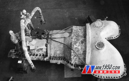
Motor upper cylinder - Figure 1 (left) 
Motor upper cylinder - Figure 1 (right) 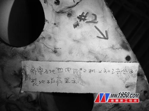
Defect location - Figure 2
2. Structural characteristics of steam turbine block and characteristics of cast steel materials
(1) Structure characteristics of cylinder block ZG20CrMo is a pearlitic heat-resistant cast steel, which is widely used in the turbine block of high power equipment and the shell of high pressure valve. Since the high-pressure steam temperature of the cylinder is 535 ° C and the pressure is 0.9 MPa, the high-pressure steam from the inlet of the high-pressure cylinder through the intermediate pressure cylinder to the outlet of the low-pressure cylinder exceeds 500 ° C, and the low-pressure cylinder end is subjected to external pressure, working pressure and temperature under vacuum. There is a gradient change in the field, so the force on the cylinder wall is also changing. Due to the large size of the cylinder casting, it is a closed or semi-closed rotary housing. The diameter, cross-sectional area and shape of the housing vary greatly. The wall of the steel casting is thicker and the wall thickness changes greatly. There are also defects such as loose casting, slag inclusion, pores, etc., which are prone to cold cracks, hot cracks or high-temperature steam blowing grooves and defects during long-term high temperature and high pressure and alternating load, which affect safety production.
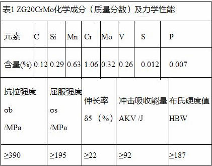
(2) Analysis of weldability of pearlitic heat-resistant steel and filler metal ZG20CrMo heat-resistant cast steel is required to have sufficient long-lasting strength, high-temperature oxidation resistance, strong resistance to hydrogen corrosion and good structural stability. Steel contains chromium, molybdenum, vanadium, tungsten and other elements (see Table 1 for chemical composition) to improve the stability of supercooled austenite. The heat affected zone has a tendency to harden. With the increase of Cr and Mo content, steel Oxidation resistance, high temperature strength and sulfidation resistance are also increased. However, the welded joints of pearlitic heat-resistant steel have many chemical compositions, metallographic structures, stress distribution fields and performance non-uniformities. This can be done by welding processes and selecting suitable welding materials to reduce welding heat input to control hardening and softening problems in the near seam area. For example, the selection of welding materials that ensure the weld bead performance is matched with the base metal to ensure that the weld should have the necessary heat strength to ensure that its chemical composition and stress requirements are close to the parent metal. The weld metal has a slightly lower carbon content and lower mechanical properties than the parent metal. The use of small welding parameters and a reasonable groove form to control the fusion ratio can reduce the metallographic structure of the welded joint during long-term use during welding and at high temperatures. Thereby reducing the dilution of the weld metal alloy content and avoiding the carbon migration and the martensite structure of the weld metal, and reducing the undesirable mutual metallurgical reaction between the two base metals to control, such as the formation of intermetallic compounds, low melting point Crystals, etc. Therefore, the chemical composition of the base metal and the filler metal, the welding method, the weld bead level, the welding process, and the post-weld heat treatment all have an influence on the structural unevenness of the welded joint of the metal composition. Since the post-weld heat treatment can reduce the residual stress and improve the comprehensive mechanical properties of the welded joint, it will cause new thermal stress in the joint during the cooling process, and it will easily cause cracks due to plastic deformation and stress increase. The preheating temperature required for the transition between the base metal and the filler metal is selected to minimize the various thermal stresses caused by the difference in linear expansion coefficient between the base metals.
3. Selection of filler metal materials
According to the chemical composition comparison between the base material of the cylinder and the metal filled metal, A507 stainless steel electrode (see Table 2 for chemical composition) is used as the filler metal for the cylinder.
Table 2 Chemical composition of molten metal (mass fraction) (%)
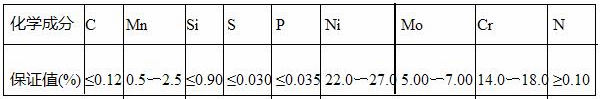
A507 is a pure austenitic Cr16Ni25Mo6 electrode for alkaline coatings. Meet the GB E16-25MoN-15 standard. The amount of CaO in the alkaline slag is large, the ability of the slag to desulfurize is strong, and the ability of the deposited metal to resist hot cracking is strong. Moreover, the basic electrode has low oxygen and hydrogen content in the weld metal, less non-metallic inclusions, and high plasticity and impact toughness. According to the value defined by the chemical composition of the molten metal, the A507 stainless steel electrode has high chromium and nickel content, good plasticity and crack resistance, and can avoid cracks caused by brittle hardened structure. The welding process and parameters determined by the weldability analysis shall be strictly followed.
The chemical composition of the cylinder and A507 is calculated and substituted into the Schaeffler organization diagram, as shown in Figure 3.

Talking about the repair welding process of the steam turbine generator set cylinder - Figure 3
Available from the coordinates:
Chromium equivalent (cylinder) = 1.06 + 0.32 + 1.5 × 0.29 = 1.833%;
Nickel equivalent (cylinder) = 30 × 0.12 + 0.5 × 0.63 = 3.915%;
Chromium equivalent (electrode) = 14 + 7 + 1.5 × 0.9 = 22.35%;
Nickel equivalent (electrode) = 22 + 30 × 0.1 2 + 0.5 × 2.5 = 29.85%;
The weld structure obtained by using the austenitic Cr16Ni25Mo6 stainless steel electrode is a pure austenite with a small amount of ferrite structure and weld center near the weld line. This kind of structure can not only reduce the tendency of hardening to avoid hot cracks, but also has good corrosion resistance and heat resistance, and can meet the performance requirements of weld metal.
The use of high chromium nickel stainless steel welding consumables has the following advantages:
(1) It is basically consistent with the chemical composition of the cylinder metal to prevent the diffusion of alloying elements and reduce the high temperature performance of the welded joint. The composition of the nickel-based weld can be changed to a large extent, which reduces the influence of the welding parameters on the dilution ratio of the weld, and reduces and eliminates the influence on the weld composition.
(2) The use of austenitizing stable and stable filler metal will improve the comprehensive mechanical properties of the transition zone. The content of chromium and nickel is relatively high, and the mechanical properties are similar, especially paying attention to the high temperature performance. If the weld joint is too high in strength after welding, the plastic bending angle will become smaller and even cracks will be formed.
(3) It has physical properties compatible with the base metal. Although the thermal expansion coefficient of the austenitic welding material is larger than that of the base metal, the low carbon content and good toughness of the welding consumable can effectively reduce the welding residual stress. To avoid cracks caused by the formation of brittle hardened structures. Low carbon content welding consumables improve the heat treatability, impact toughness, and thermal strength of the weld metal.
(4) It can ensure the integrity of the weld and can withstand the dilution of the base metal without generating such defects as pores, inclusions and harmful metal compounds, ensuring that the weld metal has the required comprehensive properties such as heat strength and heat resistance. Corrosion resistance.
(5) The content of austenite forming elements in the welding material is high, which can reduce the width of the transition layer and avoid tissue embrittlement. Maintains tissue stability under conditions of use. Chromium and nickel are compatible with hydrogen and carbon. Nickel-based welds are not sensitive to hydrogen and have high solubility to hydrogen. They not only overcome the harmful effects of hydrogen on the base metal, but also prevent hydrogen cracking, and reduce carbon diffusion and carbide precipitation. .
(6) The side of the metal cylinder with a small preheating coefficient of expansion, and the filler metal or transition section with a coefficient of linear expansion between the two base metals, which reduces various types of linear expansion coefficient between the base metals. Thermal Stress. Low temperature preheating reduces the thermal stress caused by the difference in thermal expansion coefficient between the base metal and the filler metal, even if this thermal stress cannot be completely eliminated.
(7) Guarantee the use performance of the welded joint, that is, to ensure good mechanical properties and comprehensive performance of the weld metal and the base metal.
4. Preparation before welding
(1) Ultrasonic or magnetic particle non-destructive testing method is used to find the depth, length and direction of the cylinder looseness and crack defects before welding.
(2) The crack is determined according to the crack property, and the crack is required to be deep. According to the crack depth, the crack is further extended during the repair process. The hole is drilled with a diameter of 6 to 12 mm at the front of the crack of 5 to 10 mm, and then the defect crack is mechanically treated.
(3) It is best to process the U-shaped groove. The bottom of the groove should have rounded corners with a radius of not less than 5mm. No sharp corners and dead angles are allowed. The root of the crack-proof hole should also be ground into a gentle slope. The inclination of the groove should be >15°. Because the defect is at the near edge of the cylinder, the casting inclusions, blisters, and other defects in the cylinder during the trimming process should be polished and removed, and finally the shape shown in Figure 4 is formed.
(4) The surface of the grooved cylinder of the repaired groove is polished with sandpaper, and the magnetic powder or colored metallographic phase is detected. It is thoroughly checked that there are no defects such as groove marks and cracks in the groove and the surrounding area.
(5) In order to ensure the welding quality, the ambient temperature should not be less than 10 °C, and windproof measures should be taken at the same time. You can start repair welding work.

Positioning block - Figure 4
5. Repair welding process
(1) Using ZX7-400 electric welding machine, prepare A507 stainless steel welding rod φ3.2mm, pre-welding drying temperature 250 °C, heat preservation for 1h, and put it in a dry insulated barrel.
(2) Before welding, use the oxyacetylene flame to evenly and slowly heat the groove and the surrounding area (as large as possible) to 120~150 °C, and the heating range around the repairing zone is as large as possible.
(3) Minimize the time during which the soldered metal contacts each other in the liquid state to prevent or reduce the formation of intermetallic compounds. During welding, the heating and contact time of the material should be as short as possible, and the arc heat source of the welding rod can be biased toward the side of the welded cylinder, and the straight line of the welding rod is not oscillated, DC reversed, small current, narrow bead, and multiple layers are short. Arc welding, arc voltage 14~24V, welding current 80~110A.
(4) It is required to guide the arc in the groove or in the weld bead and ensure that each weld bead is well fused.
(5) Firstly weld a layer of welding layer (thickness 2~4mm) from the inside of the groove width and depth. After welding, do not hit the coating immediately. After cooling, use non-destructive testing of coloring to carefully check the repairing zone. Defects such as cracks should be removed immediately. After the test is completed, the weld can be reheated to 100 °C before the groove fill can be welded.
(6) The position of each layer of welding arcing should be staggered, and the arc should be controlled to prevent cracking of the crater. The layer temperature is not higher than 100 ° C, so that it has a short residence time in the sensitization temperature zone, which is beneficial to prevent intergranular corrosion. After each layer is welded, the coating and edge spatter should be cleaned and checked for weld defects.
(7) The first layer and the fill layer weld bead are properly hammered to reduce the filler metal and cylinder restraint stress by loosening the weld bead, but the cover layer is disabled.
(8) The cover layer should be slightly higher than the joint surface. The control should not have the undercut. Immediately after welding, it should be covered with asbestos cloth and slowly cooled to room temperature for surface processing.
6. Post-weld quality inspection
(1) The welding surface should be higher than the plane of the joint surface of the cylinder, and the two sides of the fusion line should be smoothly transitioned. The repair welding seam must not have undercuts, unfilled, slag, cracks and other defects.
(2) After grinding and repairing the repaired area, check the flatness of the joint surface with a long flat ruler. If necessary, install the test block of the cylinder block and check the joint surface with a feeler gauge to make the joint surface of the upper and lower cylinders flush to meet the sealing requirements. To avoid the occurrence of deformation of the cylinder joint surface caused by repair welding.
(3) Finally, the surface of the repaired weld area after leveling is subjected to surface coloring inspection, and it is required to achieve no defects.
7. Precautions
(1) When the groove is trimmed with carbon arc gouging before welding, a mechanical method is used to remove the carburizing and copper layer of about 0.5 mm thick inside the groove.
(2) The welding process uses a small heat input to reduce deformation, welding residual stress and improve the processing performance of the joint.
(3) During the welding process, attention should be paid to the fusion wettability between the groove and the base metal, and defects such as slag inclusion, unmelting and crater cracking cannot be produced.
(4) Magnetic powder testing cannot be used after welding.
8. Conclusion
(1) The repair welding shall be carried out according to the value defined by the chemical composition of the deposited metal, and the welding material with high content of chromium and nickel and good plasticity and crack resistance shall be selected.
(2) Determine the welding process and specifications according to the stainless steel with poor weldability, and the metal with low expansion coefficient of low temperature preheating.
(3) The repair welding shall be determined according to the size, length, length and distribution of the defect, the depth and width of the weld zone, the thickness of the weldment, the construction conditions, the use environment and whether the weld can be reversed.
(4) According to the welding performance of the material, the nickel-based welding rod welding cold welding method is adopted, which satisfies the long-term operation requirements of the unit, saves a lot of cost and time, and achieves satisfactory results.
ZHejiang Sealand Technology Co., Ltd. is a trustworthy manufacturer of LNG Mass Flow Meter, LNG Mass Flowmeter, LNG Flow Meter, LNG Flowmeter, LNG meter, ATEX, IECEx & CE approved.
We are the only Chinese brand who gets ATEX, and we get it from TUV SUD, the most authoritative institute for ATEX. Our meter passed all tests carried out by TUV without any modification. Their only suggestion is to replace the cable entry device with a ATEX approved one; thus, please rest assured that we produce our meter with high standard :)
Besides, Sealand meter and calibration lab are approved by CNAS, member of ilac in China.
The 1'' flow meter specification is as follows,
|
Specifications of Coriolis Mass Flow Meter |
|
|
Model No. |
CG-25 |
|
Max. flow rate |
200kg/min |
|
Nominal diameter |
25mm( 1 inch) |
|
LNG accuracy grade |
±0.2% |
|
Zero stability |
0.62kg/hr |
|
Repeatability |
0.05% |
|
Warranty |
2 years |
|
Temperature accuracy |
±1°C ±0.5% of reading |
|
Fluid temperature |
-200~160°C |
|
Packing |
1set/carton |
|
Package size |
665*660*315mm |
|
G.W. |
23kgs |
Please feel free to contact us if you need any other size!
LNG Mass Flow Meter, LNG Mass Flowmeter, LNG Flow Meter, LNG Flowmeter, LNG meter
Zhejiang Sealand Technology Co., Ltd. , https://www.sealandflowmeter.com