In recent years, high-temperature, high-pressure corrosion-resistant petrochemical and coal chemical pressure vessels have become larger, and for some large-scale major equipment based on comprehensive consideration of strength and corrosion resistance, the inner wall often requires surfacing austenitic stainless steel or nickel-based alloy. Therefore, in order to improve production efficiency and product quality, submerged arc surfacing technology is widely used in large-area surfacing of container inner walls. At the same time, due to the special shape of the shape of the cone in the cone part of the container, it is the experience of successful submerged arc surfacing welding rarely encountered in China. Combining with the actual situation of the factory, starting from the feasibility and reliability of production, starting from researching and manufacturing the corresponding professional equipment, on the basis of formulating reasonable processes and parameters, selecting the inner wall surfacing welding with the submerged arc surfacing, Improve production efficiency and ensure the quality of the product.
1 Overview
A factory contracted the production of lock cylinder containers for coal chemical projects. The lock bucket container category was Class II (SAD), and the container body material was 16MnR surfacing 00Cr17Ni14Mo2. The design parameters are shown in Table 1.
Table 1 Design parameters
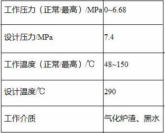
The inner diameter of the container is 2190mm and the length is about 8586mm. The corrosion-resistant composite layer with a thickness of 5mm is required to be surfacing. The welding volume is large and the welding is difficult. The cone is between DN2200 and DN350mm and the length is 2170mm. 85/40+5mm, and the quality of surfacing welding is very strict. The surface of the weld is required to be smooth after surfacing. The surface without processing should be smooth. The depression between two adjacent welds should not exceed 1mm. The unevenness of the weld joint. ≤ 1mm, the structure of the device is shown in Figure 1.
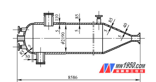
Figure 1 Schematic diagram of the equipment
(1) Main surfacing technology requirements Before the surfacing, the surfacing surface of the base metal shall be tested by 100% MT without any cracks or defects. 2 Each layer of weld overlay must be tested for 100% PT, and 100% UT should be tested after surfacing. 3 After the completion of the surfacing of the transition layer, the stress relief heat treatment is performed, and then the surface layer is deposited. 4 The chemical composition within 3mm of the surface of the surfacing layer should be consistent with the chemical composition of the surface layer. 5 Before the heat treatment, the ferrite content of the weld overlay layer should be determined, and the ferrite content is required to be 4% to 10%.
(2) Features of electrode surfacing Welding with electrode surfacing is a cost-effective and fast process for surface modification. It has lower dilution rate and higher deposition rate than other surfacing techniques, and is better. Surfacing properties.
Mainly in the following aspects:
First, in the case of pole surfacing, the arc moves back and forth in the extreme portion of the belt, and the resistance heat generated by the strip is relatively small. Therefore, a large current can be used for surfacing, thereby achieving high production efficiency.
Second, the electrode stack welding can control the penetration depth within 1 mm, so the dilution rate is very low and the quality of the weld overlay layer is high.
Thirdly, the melting ratio of the electrode surfacing flux to the solder ribbon is 0.4 to 0.5, which is 1/2 of the filament, so the flux is saved, thereby reducing the production cost.
Fourth, the burning of the alloying elements in the strip and the increase of the unfavorable elements are extremely small, and the plasticity and toughness of the surfacing layer are higher than that of the submerged arc welding.
Since the carbon diffusion layer of the joint fusion zone is narrow and the martensite zone width is small, the joint fusion zone performance is superior to that of the silica electrode submerged arc surfacing.
2. Selection and chemical composition of surfacing materials
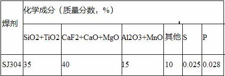
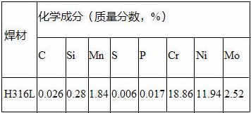
According to the pattern requirements, the surfacing layer transition material is E309MoL-15, the surface layer material is E316L-15, the transition layer is selected as the H309LMo, the surface layer is H316L welding material, the specification is 60mm×0.5mm, and the flux is SJ304. Its chemical composition is shown in Table 2 and Table 3.
Table 2 Chemical composition of the ribbon
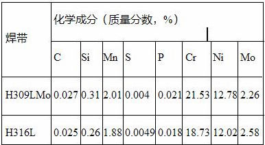
Table 3 Flux chemical composition
3. Surfacing process evaluation
The electrode stacking welding selects a large current and voltage to ensure the thickness of the surfacing layer, and the rapid welding can improve the productivity. However, according to the literature analysis, the current and voltage increase, and the dilution rate increases. The welding speed is increased and the dilution rate is also increased. In order to ensure that the surfacing has a small dilution rate, the welding parameters should not be too large.
In the process of surfacing, the amount of pressure is too small, the arc directly acts on the base metal, the amount of molten metal of the base material is large, and the dilution ratio of the weld is high. At the same time, the amount of depression between the weld beads, that is, the defect of the channel is most likely to form stress concentration. . The amount of pressure is too large, making the surface of the weld uneven and wasting the welding material. After many adjustments, the most stable and well formed pressure is 8~10mm.
The surfacing process qualification is carried out in accordance with JB 4708-2000 "Steel Pressure Vessel Welding Process Evaluation" in the corrosion resistance surfacing process evaluation rules, the test piece size is 300mm × 600mm × 25mm, the best welding parameters and assessment results, as shown in Table 4 Shown.
Table 4 Welding parameters and assessment results
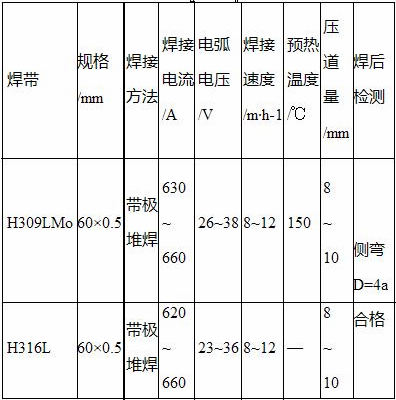
Table 5 Surface chemical composition
4. Cone surfacing design
Due to the large weight of the container and the inclusion of a cone, it is usually the case that the cone will "slip" when it is rotated on the general tire, which seriously affects the build-up and quality of the weld; at the same time, due to the difference in diameter. Therefore, it is necessary to start from ensuring the uniform rotation of the cone, determine the appropriate surfacing parameters, develop a suitable welding equipment, and develop a tire for the cone-stack welding as shown in Figure 2 and Figure 3. At the same time, in view of the fact that the cone will have a smaller speed from the big end to the small end, and the circumferential distance of the nose is smaller, the welding parameters of the decreasing nature are determined. Firstly, the welding current and the arc voltage are gradually reduced to ensure the dilution rate. The welding speed is controlled to gradually slow down to ensure a lower welding heat input during the welding process, which is generally reduced to one stage per 20A and 3V. After welding for 3~5 turns, re-select the dry end of the strip to keep it at 30~40mm, and for the convenience of arc-ignition, cut the taper at the end of the strip to a cone of about 120°, in the cone When surfacing, select the tire set shown in Figure 3. Its structure should be similar to the shape of the cone. When using the tire for surfacing, the small end of the cone is horizontal with the big end, that is, the inner wall is rotated no matter how They are all at a horizontal distance from the nose. The adjustment of the height is determined by the Screw at the rear. The large end is the active part, the small end is the follower and the smoothing is prevented. As shown in Fig. 4, the cone is being welded. body. The design of the cone surfacing tire has been applied for national patent, patent number: ZL200820111544.5.
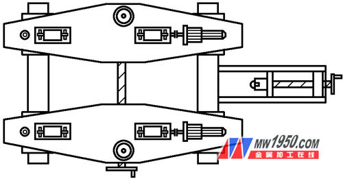
Figure 2 shows the barrel surfacing
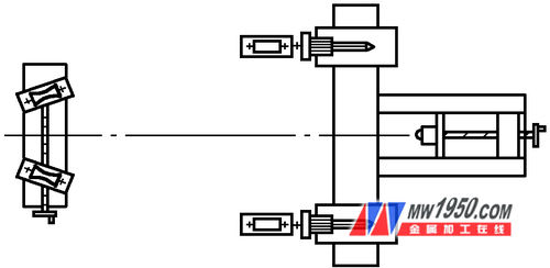
Figure 3: Cone surfacing 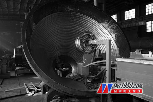
Figure 4 Field cone surfacing
5. Surfacing process development
Based on the above reasonable surfacing evaluation, the following surfacing process was developed.
(1) Before the surfacing welding, 100% magnetic powder inspection shall be carried out on the surfacing surface of the base metal before surfacing, to ensure that there is no crack on the surfacing surface, and the surfacing welding of the base metal is smoothed by the weld, and it is qualified by 100% RT. Surfacing can be done at the rear. The surfacing surface should be clean, free of oil and other impurities that affect the quality of the surfacing.
(2) Before the preheating surfacing welding, the base metal should be preheated, and the preheating temperature is controlled at about 150 °C. This can not only delay the post-weld cooling rate, reduce the harmful temperature gradient, ensure the diffusion of hydrogen in the weld can escape in time, but also reduce the welding residual stress and the restraint of the welded structure. For the entire cone, make an integral heating box, preheat it to the required temperature, and then place the tire on the welding. When welding, try to maintain continuity to ensure sufficient interlayer temperature; and for the joint (or open forging) The Harvard-type heating sheet (internal heating type, external heating type) is used for heating, which is characterized in that no wrapping is required, and heating and welding can be performed simultaneously. The heating form is shown in Figure 5.
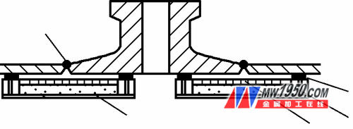
Figure 5 shows the heating of the welded part before welding
1. Insulation layer 2. Welding part 3. Magnet 4. Insulation strip 5. Track type heating sheet 6. Iron sheet
(3) In the transition layer surfacing welding, the qualified welding consumables are used. The welding belt is H309LMo, the flux is SJ304, and the welding is carried out in strict accordance with the assessed process parameters. During the welding process, the inter-layer temperature is guaranteed to be 150-250 ° C. After the surfacing of the transition layer is completed, 300-350 ° C × 2 h post-weld dehydrogenation treatment is performed, followed by 100% PT detection. Then, the whole cone is subjected to post-weld stress relief treatment of (620 ± 20) ° C × (2.5 ~ 3.0) h according to Fig. 6.
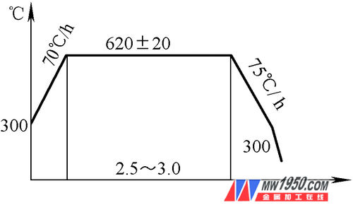
Figure 6 Stress-relieving heat treatment curve after transition layer welding
(4) After the surface layer surfacing welding layer is tested, the surface layer surfacing is carried out, and the welding tape H316L and the flux SJ304 are selected. Welding is carried out in strict accordance with reasonable parameters in the assessment. Ensure that the thickness of the weld overlay is 5mm. After the surface layer surfacing is completed, 100% PT test is performed, and 100% UT is detected after passing the test.
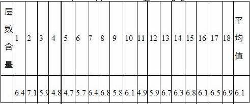
(5) Ferrite testing of the surfacing layer After the non-destructive testing of the surfacing layer is completed, the ferrite content of the surfacing layer is detected, and a total of 18 detection points are taken. The test results are shown in Table 6. The results show that the ferrite content is within 4% to 10%, which meets the requirements.
Table 6 Ferrite content (mass fraction) of surfacing layer (%)
6. Welding defects and preventive measures
(1) Strict implementation of welding parameters Due to excessive current during the transition layer surfacing, the welding speed is small, resulting in serious dilution rate of the surfacing layer, and the hardness of the surfacing layer cannot meet the requirements. Therefore, the welding parameters must be strictly implemented during surfacing. Maintain reasonable values ​​and minimize heat input.
(2) Strict implementation of insulation measures Due to uneven control of preheating temperature during surfacing, too high or too low, and large temperature fluctuations during surfacing, cracks may occur, so the insulation measures during surfacing shall be strictly enforced. After the completion of the surfacing of the transition layer, it is necessary to heat treatment according to the process in time.
(3) Strictly cleaned before welding, because the surface impurities of the weldment are not cleaned, or the slag and the coating are not cleaned, resulting in welding defects. Therefore, when the lower layer is welded, the upper weld bead should be removed to remove slag and medicine. Leather and other debris.
7. Conclusion
(1) Surfacing the product according to the above process, and performing non-destructive testing according to JB4730 to ensure the quality of surfacing.
(2) The products welded by this welding process, the testing performance and other indicators are in line with the standards and related requirements, which proves the correctness of the above process.
(3) Formulate a reasonable cone tire to ensure the quality of product surfacing and the successful completion of product surfacing.
(4) Selecting H309LMo and H316L welding strips to match SJ304 flux, and adopting reasonable welding parameters, as well as pre-weld preheating and post-weld heat treatment measures, are the key to ensure the quality of surfacing.
Organization Rack is made of high quality 304 stainless steel, It is easier to clean without rust, safe, healthy and durable, Prevent rust or chemicals from contaminating food and damaging health. Suitable for putting fruits vegetables and bread in kitchen, dining and bar.
Humanization Design: The stainless steel Fruit Basket are designed with no borders and hidden solder joints, will not cut your hand, and does not hang fabric, more convenient cleaning. Start with the details and let the family eat more reassuring food.
304 Stainless steel basket,2-tier fruit basket,2 layer fruit basket,Stainless steel mesh basket,picnic basket
Shenzhen Lanejoy Technology Co.,LTD , https://www.baking-rack.com