At present, the number of elevators in China has grown rapidly with the increase of high-rise buildings, providing great convenience for production and life. How to ensure that each elevator can operate reliably, timely detection of faults and troubleshooting, has become the key to improving the level of property management and elevator technology. The quality of elevator operation is directly determined by the function of the monitoring system. At present, the centralized monitoring system of domestic elevators adopts fixed transmission or CAN bus field data acquisition, while the maximum transmission distance of CAN bus is 10 km. It is necessary to realize centralized monitoring of elevators in a wider range. , you need to increase the system hardware equipment. To this end, a remote elevator monitoring system based on GPRS technology is designed. Because the wireless GPRS network has the outstanding features of always-on and high transmission rate, it can reduce the system operation and maintenance cost to the minimum under the premise of ensuring timely and accurate data transmission.
1 Introduction to GPRS
GPRS is the abbreviation of General Packet Radio Service. It is a wireless packet switching technology based on GSM system, providing end-to-end, wide-area wireless IP connection. GPRS introduces two new network nodes (GPRS service support node SGSN and GPRS gateway support node GGSN) in the GSM system and makes software upgrades. It can establish a data communication chain between the terminal device and the server attached to the Internet. road. The technical advantages of GPRS network are mainly reflected in two aspects, the combination of user data and wireless network resources and transparent transmission of data based on IP protocol. Compared with the original GSM, GPRS has obvious advantages in the bearer and support of data services: 1) Through the multiplexing of multiple GSM time slots, the supported data transmission rate is higher, the theoretical peak value is 17 Kbps; 2) Different network users share the same set of GPRS channels, but only when a user needs to send or receive data will occupy channel resources. In this way, through multi-user service multiplexing, channel resources are more effectively utilized, which is especially suitable for bursty and frequent small-flow data transmission, which is well adapted to the bursty characteristics of data services; 3) GPRS charging method is more Flexible, support for flow rate; 4) Unlike Wireless Application Protocol (WAP) technology, GPRS can provide users with transparent IP channels at any time, which can directly access all sites and resources in the Internet; 5) Adopt channel multiplexing technology, Every GPRS user can always be online; in addition, GPRS can also support voice calls while data transmission is in progress.
2 system composition and principle
2.1 System composition principle
The composition of the GPRS-based elevator monitoring system is shown in Figure 1. The system consists of local PLC, information acquisition terminal, GPRS data transmission and remote monitoring center.

Figure 1 Elevator monitoring system structure
Firstly, the embedded microcontroller of the terminal device communicates with the local PLC to obtain the operating state parameters of the elevator, processes the obtained data, and then sends the processing result to the GPRS network through the GPRS module in the format of the protocol data frame through the serial port. in. Since the GPRS network and the Internet are both based on the IP protocol and are connected to each other, the data processing result of the terminal is transparently transmitted to the remote monitoring center via the GPRS network. The host of the monitoring center accesses the Internet and has a fixed IP address. The terminal first logs in to GPRS to obtain an IP address, and then sends the IP address to the host monitoring center. Since the IP address of the terminal is the IP address of the GPRS intranet, it is necessary to perform network address translation through the NAT server of the GPRS network to realize two-way communication between the host and the terminal. When the host monitoring center receives the IP address sent by the terminal, the network of the terminal and the monitoring center is connected, and the query command or control command of the monitoring center can be sent to the GPRS module through the Internet and the GPRS network, and then The GPRS modules are transmitted to the terminal devices and operated on them to enable remote monitoring of the elevators on the embedded platform.
2.2 System terminal hardware design
The MCU uses NPC's LPC21480. The LPC2148 is based on a 32/16-bit ARM7 TDMI-S core microcontroller that supports real-time emulation and embedded tracking. It features high performance and low power with a wide range of peripheral resources for up to 60 The CPU operating frequency of MHz.
The GPRS module uses Huawei's EM310. EM310 is a GSM/GPRS dual-band wireless module supporting EGSM900 and GSM1800 dual-band; providing data, voice, SMS, and fax functions; standard protocol authentication, compatible with GSMphase2/2+ protocol standard: providing voice interface (low power consumption) Supports voice coding of FIR, EFR, HR and AMR; supports hands-free calling, provides echo suppression function; supports standard and extended AT commands. In addition, the EM310 module has a built-in TCP/IP protocol stack that is controlled by AT commands and makes it easy for applications to access the network. The advantage of this solution is that it does not require application vendors to implement their own TCP/IP and PPP stacks, thus minimizing the cost and time required to integrate network connections into a new or existing application. The EM310 interface circuit is shown in Figure 2. For the EM310 to work stably, the power supply voltage should be between 3.4 and 4.7 V, and the ripple of the power supply should be small; the module start signal must be held low for more than 50 ms at the IGT pin.
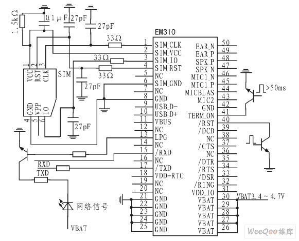
Figure 2 EM310 interface circuit
The data storage chip uses CATALYS's serial CMOS E2PROM - AT24C02, advanced CMOS technology to substantially reduce the power consumption of the device. The device contains 256 octet of memory and has a 16-byte page write buffer. The AT24C02 supports IC, Bus Data Transfer Protocol IC, which specifies any device that transfers data to the bus as a transmitter. Any device that receives data from the bus is a receiver. Data transfer is controlled by the master that generates the serial clock and all the start and stop signals. Both the master and slave can act as either a transmitter or a receiver, but the master controls the mode in which data is transmitted (transmitted or received). AT24C02 interface circuit shown in Figure 3.
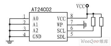
Figure 3 AT24C02 interface circuit
3 software design and implementation
3.1 AT command
The AT command set is sent from a Terminal Equipmen (TE) or a Data Terminal Equipment (DTE) to a Terminal Adapter (TA) or a Data Circuit Terminal Equipment (DCE). Through the TA, the TE sends an AT command to control the function of the mobile station (MS) and interact with the GSM network service. The user can control the call, text message, phone book, data service, fax, etc. through the AT command.
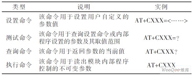
The AT command is an interface standard, and its instruction format is relatively fixed. The instruction is prefixed with AT or at, with a carriage return
Table 1 AT command type
3.2 EM310 connected to the monitoring center AT command design and implementation
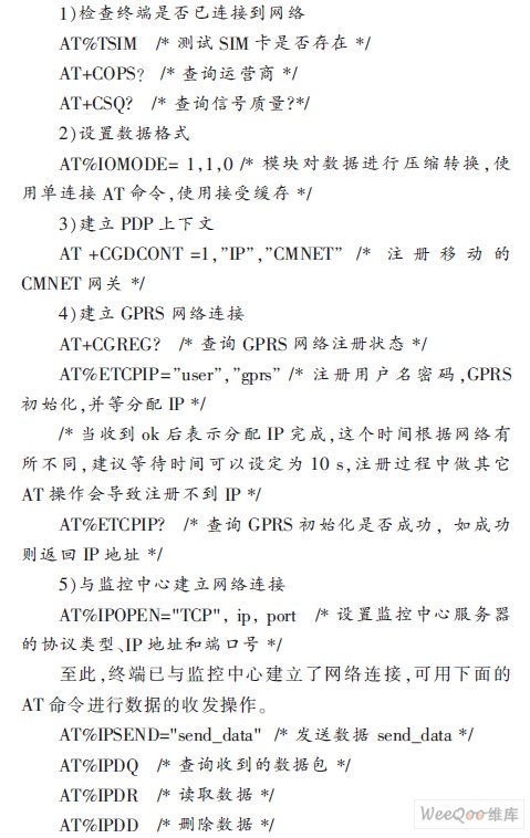
The TCP/IP protocol is embedded in the EM310, and the control module (this design uses LPC2148) provides the API interface for accessing the GPRS network and accessing the Internet in the form of AT commands. Connecting to the monitoring center via EM310 generally involves the following steps (if not specified, the AT command returns OK for success and ERROR for failure):
3.3 Terminal Software Design
The ARM module is programmed to implement the IP module related instructions and the GPRS module related instructions. Complete the terminal's Internet access, establish connections, and send data. Software development using C language and IAR for ARM compilation environment. The program is divided into main program, terminal serial communication program and elevator signal acquisition/control program. The main program completes the operation of GPRS module initialization and network connection, the serial communication program completes the data transmission between the GPRS module and the monitoring center computer, and the elevator signal acquisition/control program completes the collection of the elevator running state and fault information and the analysis and monitoring center command, operation The operation of the elevator. Several functional modules are designed in combination with the functional requirements of the terminal, as follows:
1) The parameter configuration module implements the function configuration of the local terminal, the system initialization, the device number, the monitoring center IP address, and the heartbeat packet time setting.
2) The local control module accepts the instruction of the monitoring center and transmits the elevator running command to the PLC through the communication between the terminal and the local PLC to realize the operation of the remote operation elevator.
3) GPRS communication transmission module to realize the data "transparent transmission" function. The terminal temporarily stores the data to be uploaded in a buffer of 1 024 B, and the main loop program detects that the upload data identifier is set to start the data uploading module. For the received data from the monitoring center, the method of directly transmitting the AT read command in the main loop program is used to extract the data.
4) The GPRS line maintenance module sends a fixed data frame to the monitoring server every time the heartbeat packet arrives, and then judges that the defined handshake data packet is received, or if the receiving timeout occurs, re-login to the GPRS to implement the terminal. Reconnect after disconnecting the network connection from the server.
The lower machine software flow is shown in Figure 4.
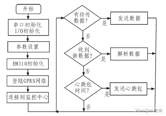
Figure 4 lower computer software flow chart
3.4 Monitoring Center System
The configuration of the monitoring center server is also a key part of the system. It has the functions of terminal query, control, alarm and data saving and printing. It is responsible for monitoring the data sent by multiple remote terminals via the Internet and periodically saving important data to the central database. in. The function of the monitoring center is large and complex. Since the system is based on an IP address and the Internet, in order to protect the security of communication data in the network, communication data needs to be encrypted.
4 Conclusion
In order to realize the long-distance transmission of signals in the elevator monitoring system, a monitoring system based on GPRS network communication technology and computer control technology is proposed. The method of constructing a system framework combining wireless communication network and ARM embedded is given. Hardware design and functional design of each part. The remote monitoring system based on GPRS communication technology will have a wider application prospect.
references:
[1]. GPRS datasheet http://
[2]. PLC datasheet http://
[3]. LPC2148 datasheet http://
[4]. EFR datasheet http://
[5]. AT24C02 datasheet http://
:
LED Outdoor Lights including Pixel Light, Dot Light , Linear Light, Wall Washer , Spot Light , Flood Light, In-ground Light, Underwater Light,for outdoor lighting,architecture lighting,landscape lighting, etc.
LED Outdoor Lights,Dot Light,Linear Light,Wall Washer,Spot Light,Flood Light,In-ground Light,Underwater Light
StrongLED Lighting Systems (Suzhou) Co., Ltd. , https://www.strongledcn.com