introduction
The urban water supply pipe network is a pipeline network system with complex structure and large scale, which is the bloodline for the city to survive. In recent years, with the advancement of technology and capital investment, most water supply companies have established a water supply data monitoring and control system (SCADA) to achieve monitoring of water and raw water transport systems, monitoring of water purification structures and process equipment, and pressure measurement of water supply networks. Function, but the valve opening and closing and adjustment must also be done manually by the operator to the site. Pipe network valve is an important facility in the water supply system. It plays a role in regulating, shutting down, regulating the flow of water supply, pressure and changing the flow direction. It is an important guarantee for the smooth distribution and maintenance of the water supply system and the repair, maintenance and transformation of the pipe network. . Therefore, as an important equipment in the pipe network, how to better manage the valve is becoming more and more important for the construction and operation management of the pipe network.
1 Water supply network monitoring system
Usually, the water supply pipe network monitoring system consists of four parts (as shown in Figure 1): pipe network parameter measurement, valve intelligent control system, pipe network monitoring center, valve electric actuator. The principle is to remotely collect the data of the pipe network system through the sensor, and transmit the signal to the enterprise pipe network control center and the valve intelligent control system via wired or wireless means. The valve intelligent control system controls the electric motor according to the timely feedback monitoring data transmitted. The actuator performs valve adjustment. The valve intelligent control system is the core part of the control.

2 Pipe network parameter measurement
The water supply network monitoring point generally requires measurement of pressure, flow, flow rate, and flow direction four-way data. Therefore, the site needs to configure the pressure, flow, flow rate, flow direction transmitter, and then send the parameter signal to the valve intelligent control terminal or pipe network monitoring center by wired or wireless means. The main pipeline should be measured in sections, as shown in Figure 2.

The parameter monitoring module of valve V1 is located in front of valve V2, and the parameter monitoring module of valve V2 is located in front of valve V3. In this way, the parameter monitoring module can accurately feed the parameters of the main pipeline L1, L2, ... to the valve intelligent control system and the pipe network monitoring center.
3 valve intelligent control system
The valve intelligent control system can independently process the transmitted pipe network parameter signal, and send an execution signal to the valve electric actuator according to the processed result, and can also upload the parameter to the pipe network monitoring center. The valve intelligent control system can be realized by a computer system, a single-chip microcomputer system, a PLC system, and the like. In this paper, the microcontroller is used as the control core and the design scheme for a certain measurement point is given.
3.1 Hardware Design
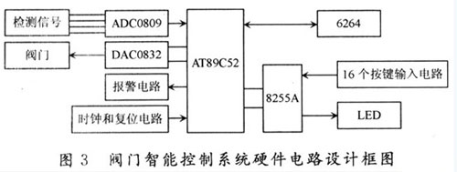
The valve intelligent control system mainly includes the main controller CPU, A/D, D/A, 8255A, 6264SRAM, key input circuit, LED display circuit, alarm circuit, clock and reset circuit, and its structure is shown in Figure 3.
The system takes AT89C52 single-chip microcomputer as the core, and the corresponding sensors will process the detected pressure, flow, flow rate and flow direction data through the transmitter, convert it into 0~5 V standard signal, and send ADC0809 chip for A/D conversion. The MCU samples once every 500 ms, and after 5 samples, median filtering is performed. After the data is converted, the actual value (engineering amount) of each parameter is displayed on the LED, and the information is sent to the pipe network monitoring center. At the same time, the detected value is compared with the given value. According to the comparison result, the output control signal is converted by the D/A converter and then outputs the control voltage, and the valve electric actuator is driven to realize the automatic adjustment of the valve.
In order to increase the flexibility of the system, a 4×4 matrix keyboard was designed. Key code 0~9 is the input digital quantity. Press “A†key to display pressure; press “B†key to display flow rate; press “C†key to display flow rate; press “D†key to display flow direction; press “E†"", cancel the alarm; press the "F" button to put the alarm.
Make your car interior look outstanding with a car interior lighting kit also known as a starlight headliner. DSPOF Lighting fibre optic headliner brings the shining starry night sky into your car. You can control the colours and the twinkle feature easily, creating an incredible cosmic vibe while you drive. If you wanna customized it,please do not hesitate to conatct with me.
Starlight Headliner Kit,star car roof,star ceiling car,star lights for car
Jiangxi Daishing POF Co.,Ltd , https://www.opticfibrelights.com