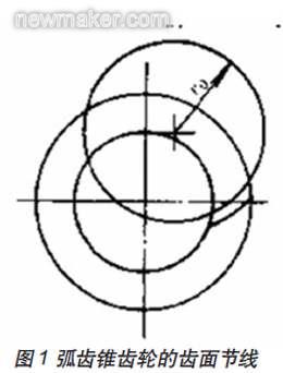
As the key component of the main reducer of the automobile drive axle, the spiral bevel gear directly determines the quality level of the whole bridge. Spiral bevel gear, the imaginary plane gear pitch of the workpiece is part of the arc. (figure 1)
Spiral bevel gears can be processed in a variety of ways, including the forming method and the forming method. Currently widely used is the exhibition method, which can be divided into single-knife double-sided cutting method, simple double-sided cutting method, fixed installation cutting method, single-knife double-sided cutting method and double double-sided cutting method.
According to the concept of imaginary plane gear, we can use the trajectory of the cutter blade to replace the teeth on the imaginary plane gear, and cut the bevel gear by the motion of the gear to mesh with the imaginary plane gear. To this end, the milling cutter disc is equivalent to the gear that meshes with it.
The double-sided milling cutter head, the average value Dg of the inner and outer tip diameter, is called the nominal diameter of the milling cutter. The nominal diameter of a single-sided cutterhead is referred to by its nominal diameter near the nominal diameter of a double-sided cutterhead.
The nominal diameter of the cutter head is selected in relation to the size of the machined gear, the helix angle, the modulus, the relative position of the top of the root cone to the top of the pitch cone, and the cutting conditions. The correct selection of the cutter diameter will directly affect the various gear teeth parameters of the machined gear, thus affecting the gear machining accuracy and machining efficiency.
Analysis of the development of milling cutter milling
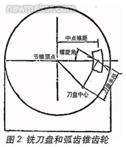
In order to obtain a better tooth contact area, the small wheel processing is generally processed by the forming method. The positional relationship between the cutter head and the workpiece during machining is shown in Fig. 2.
It can be seen from the figure that the main factors affecting the position of the cutter head are the midpoint taper (average span A), the helix angle β, and the cutter radius Rc.
When adjusting the machine tool, the pitch taper surface of the cut gear must be tangent to the pitch cone surface of the imaginary flat top gear and purely rolled, and the top selection plane of the cutter must be tangent to the root cone of the cut gear. The cutter axis is then perpendicular to the root cone surface and is inclined to the pitch cone surface by an angle equal to the angle of the root of the cut gear.
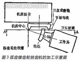
It can be seen from Fig. 3 that the cutter head is driven by the machine cradle, the center of the cradle represents the center of the crown wheel, and the center of the machine tool coincides with the apex of the pitch cone. The bending of the tooth teeth in the longitudinal direction is a circle whose radius is the same as the radius of the cutter head.
Analysis of the Influence of the Cutter Radius on the Tooth Curvature of the Tooth Length Direction
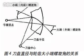
According to the concept of a spiral bevel gear, the helix angle is defined as the angle formed by the tooth face line and the pitch cone bus bar at a point on the tooth surface. It can be seen that the spiral angle of each point in the tooth length direction of the spiral bevel gear is different. Although different cutter diameter changes do not affect the midpoint helix angle, in the case where the midpoint helix angle is constant, the change in the cutter head diameter causes a change in the difference between the large end and the small end helix angle.
According to the gear design data, the formula for calculating the helix angle of the big and small ends is:
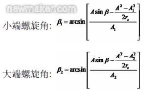
Take a pair of gear pairs in China National Heavy Duty Truck Jinan Bridge Box Co., Ltd. as an example to illustrate the effect of choosing different cutter radius:
The gear pair transmission ratio is 35/13, the modulus is 13.2mm, the shaft angle is 90°, the pressure angle is 22.5°, the tooth width is 72mm, the midpoint helix angle is 35°, the big wheel pitch circle diameter is 462mm, and the small wheel pitch circle diameter is 171.6mm. The outer taper is 246.42mm, the small end taper is 174.42mm, and the midpoint taper is 210.42mm.
When using a cutter head with a nominal diameter of 20 inches: small end helix angle: 32°23' 5", big end helix angle: 38°24' 2", the big end and small end helix angle difference is 6°57 ".
When using a cutter head with a nominal diameter of 18 inches: small end helix angle: 31°12' 46", big end helix angle: 39°28' 35", the big end and small end helix angle difference is 8°25 '49".
When using a cutter head with a nominal diameter of 16 inches: small end helix angle: 29°46' 49", big end helix angle: 40°50' 40", the big end and small end helix angle difference is 11°3 '51".
When using a cutter head with a nominal diameter of 14 inches: small end helix angle: 27°56' 46", big end helix angle: 42°38' 1", the big end and small end helix angle difference is 14°41 ' 15".
Although the change in the cutter radius has no significant effect on the point near the midpoint of the flank, it has a significant effect on the change in the helix angle of the small end and the big end. Under the premise that the helix angle of the point is constant, the closer the diameter of the selected cutter head is to the midpoint taper of the machined gear, the smaller the difference between the helix angle of the big end and the small end.
The influence of the diameter of the milling cutter on the slot width of the small gear
When the parameters of a pair of gear pairs are determined, the difference in the helix angle between the two ends of the gear teeth is the main factor determining the slot width of the small gear. The formula for calculating the cogging width of the small wheel end is:
Small round big end slot width:
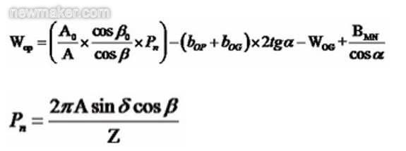
In the formula, bOP and bOG are the root height of the big end of the small wheel and the root height of the big end of the big wheel, respectively.
WOG is the large end of the big wheel.
BMN is the minimum normal gap of the big end.
Pn is the midpoint normal week.
Small round big end slot width:
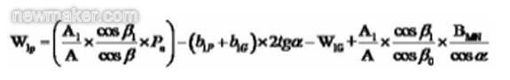
In the formula, b1P and b1G are the small wheel end root height and the big wheel small end tooth root height, respectively.
W1G is the small end small groove width of the big wheel.
In the case where the cogging width values ​​of the large end of the big wheel are the same, we can analyze the influence of the cutter diameter on the cogging width of the big end of the small wheel teeth.
As can be seen from the formula in the previous section, the change in the diameter of the cutter directly affects the helix angle of the big end and the small end of the tooth. It can be seen from the calculation formula of the cogging width of the big end of the small wheel that the cutter radius is expressed by the first and fourth spiral angle cosines in the formula. The flank clearance in the fourth term of the formula is determined by the big end and is fixed, so it can be seen that the change in the first term has a large influence on the slot width of the small gear.
When considering the wear of the precision cutting head and the surface quality of the tooth machining, the change of the finishing allowance in the big end and the small end of the small wheel is a key factor. In order to obtain a relatively uniform finishing allowance, the difference in the cogging width between the big end and the small end of the small wheel must be minimized.
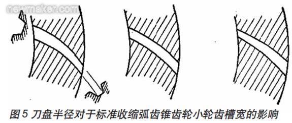
Figure 5 is a schematic diagram of the effect of the smaller cutter radius, the standard cutter radius and the larger cutter radius on the small gear groove width from left to right. When a smaller cutter head is used, the cogging width will reverse contract, that is, the small groove width of the small end of the tooth is larger than the tooth width of the large end of the tooth. When a larger cutter radius is used, the small end cogging width of the gear teeth will be too small, resulting in a significant change in the margin in the fine cut.
Effect of milling cutter diameter on tooth shrinkage of inclined root line
The inclined root line (TRL) is in the design of the spiral bevel gear, and the standard tooth root line is inclined at a certain angle, so that the gear teeth at the inner taper pitch become shorter, and the gear teeth at the large end become higher. Therefore, the small end tooth groove width can be increased, and the large end tooth groove width is reduced accordingly, whereby the root heights of both ends of the wheel of the large and small wheels are approximately the same to reduce the variation of the tooth groove width.
The sum of the large and small root angles of the inclined root line proposed by Wildhaber in 1945 is:
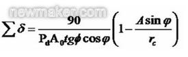
Pd is the diameter of the gear. In the root line tilting mode, although the root line can be tilted around any section on the tooth, the most applied is the root line tilt around the midpoint of the tooth width (TRLM). When tilting along the midpoint of the tooth width, the required working tooth height is maintained at the midpoint of the tooth teeth while avoiding undercutting and narrowing of the tooth tip width at both ends of the tooth. When the cutter radius is reduced,
Also reduced, when rc=AsinΦ,
Zero is the case of contoured teeth.
The inclined root line technique has the advantage of reducing the shrinkage of the cogging width of the gears using various cutter head radii. Since the choice of the top distance is affected by the widening of the cogging, the maximum available tool top distance is limited by the minimum cogging width of the teeth, so the reduction in the width of the cogging reduces the choice of the top distance. Big.
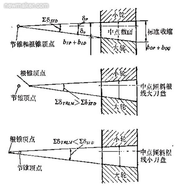
Figure 6 reflects the effect of the cutter radius on the sum of the root angles of the spiral bevel gear teeth.
Conclusion:
The influence of the parameters of the spiral bevel gear milling cutter on the geometrical parameters of the gear teeth and the strength of the gear transmission is not much domestic application. The research and exploration are not deep enough, and we need to further carry out relevant theoretical exploration and experimental research. (end)

Concerned about surprises
Tag: gear tooth cutter spiral angle spiral bevel gear milling cutter
Previous: AMF Zero Point Positioning System Application Area Report Next: Hardware Daily Problem Collection
Features and advantages of our Railed tunnel trolley, tunnel formwork system. Scientific design makes the roof and side wall surface smooth after second time lining, Optimized mechanic design makes reduce the steel cost of the formwork and save the construction cost, Standard production: full usage of standard parts, develop university of the formwork, makes the tunnel formwork to be reused more times.Modernized factory and Certificate of patent.
Tunnel Formwork Trolley,Quickly Assembled Formwork Trolley,Integrated Pipe Gallery Trolley,Pipe Gallery Formwork Trolley
Anshan Lijian Engineering Group Co. LTD , https://www.lijianformwork.com