The foam bladder tank is the main unit of the foam extinguishing system. The foam tank and the low/medium expansion foam generator construct the low/medium foam spraying system. It can also construct the high expansion total flooding extinguishing system with high expansion foam generator. It aims at fire of class A and class B, especially for fire of class B. The foam bladder tank mainly applied in occasions such as places where inflammable liquid was produced, stored and transported. It is especially suitable to put out fire caused by inflammable liquid tank or large scale of spill fire.
PRINCIPLE
The device consists of pressure tank, bladder, proportioner, pressure gauge, valves and pipeline. A pump is needed to supply pressurized water. When pressurized water flow though proportioner, a small part of water (3%-6%) flow into tank from branch pipe to press the bladder to swap out equal foam concentrate and then mix with another part of water (97%-93%) to form foam solution in proportioner and provide to foam generator.
PARAMETERS
| Proportioner Model No. |
PHY4 | PHY8 | PHY16 | PHY24 | PHY32 | PHY40 | PHY64 | PHY72 |
| Diameter (DN) | 50 | 65 | 80 | 100 | 100 | 150 | 150 | 150 |
| Mixing Ratio | 3% or 6% | |||||||
| Rated Working Pressure (MPa) | 1.2 | |||||||
| Working Pressure Range (MPa) | 0.3~1.2 | |||||||
| Rated Flow (L/S) | 4 | 8 | 16 | 24 | 32 | 40 | 64 | 72 |
| Flow Rang (L/S) | 1~4 | 2~8 | 3~16 | 4~24 | 8~32 | 12~40 | 15~64 | 17~72 |
| Pressure Drop (MPa) | ≤0.2 | |||||||
INSTALLATION
Device should be installed at places with shelter to avoid sun and rain. Ambient temperature should be within 40°C and leave enough space for operation. Device should be installed at concrete floor and fastened with anchor nuts.
Do the hydraulic test after installing. Open the tank vent valve first then fill water into bladder from concentrate draining pipe. Then close tank vent valve when bladder is full of water. Pressurize the system and keeping for 10 minutes when pressure gets test pressure, tank should have no leakage. Close water inlet valve and open water drainage valve and concentrate drainage valve to drain water away in tank and bladder. (We will do this test when products leave the factory)
Â
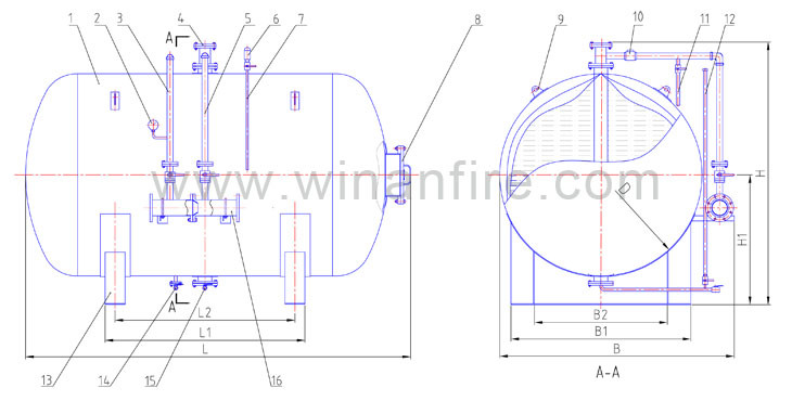
1. Tank   2. Pressure Gauge   3. Water Inlet Pipe   4.Feed Inlet   5. Concentrate Outlet   6. Safety Valve
7. Tank Vent Pipe   8. Inspection Hole   9. Lifting Lug  10. Check Valve   11. Bladder Vent
12. Liquid Indicator   13. Bracket   14. Water Drainage   15. Foam Drainage   16. Proportioner
Â
| CAPACITY LITERS | D mm |
L mm |
L1 mm |
L2 mm |
B mm |
B1 mm |
B2 mm |
H mm |
H1 mm |
WEIGHT (KG) |
| 500 | 800 | 1450 | 630 | 480 | 1250 | 705 | 400 | 1400 | 700 | 280 |
| 1000 | 1000 | 1800 | 800 | 625 | 1350 | 760 | 330 | 1600 | 800 | 350 |
| 1500 | 1000 | 2350 | 1270 | 1120 | 1350 | 760 | 340 | 1650 | 810 | 450 |
| 2000 | 1200 | 2300 | 1230 | 1025 | 1550 | 1000 | 390 | 1800 | 900 | 550 |
| 2500 | 1200 | 2650 | 1550 | 1350 | 1550 | 1000 | 400 | 1850 | 910 | 700 |
| 3000 | 1400 | 2500 | 1320 | 1120 | 1750 | 1200 | 400 | 2100 | 1000 | 800 |
| 3500 | 1400 | 2800 | 1450 | 1250 | 1750 | 1200 | 400 | 2100 | 1000 | 950 |
| 4000 | 1500 | 2750 | 1500 | 1300 | 1850 | 1300 | 500 | 2200 | 1100 | 1050 |
| 5000 | 1600 | 3100 | 1800 | 1500 | 1950 | 1400 | 850 | 2300 | 1100 | 1200 |
| 5500 | 1600 | 3250 | 1800 | 1500 | 1950 | 1400 | 850 | 2300 | 1100 | 1300 |
| 6000 | 1600 | 3400 | 1900 | 1700 | 1950 | 1400 | 850 | 2300 | 1200 | 1400 |
| 7500 | 1800 | 3500 | 2100 | 1800 | 2200 | 1800 | 850 | 2500 | 1200 | 1600 |
| 9000 | 2000 | 3500 | 2000 | 1800 | 2400 | 1800 | 1350 | 2700 | 1300 | 1900 |
| 10000 | 2000 | 3850 | 2000 | 1800 | 2400 | 1800 | 1350 | 2700 | 1300 | 2200 |
| 11000 | 2000 | 4100 | 2000 | 1800 | 2400 | 1800 | 1350 | 2700 | 1300 | 2600 |
| 13000 | 2200 | 4000 | 2350 | 2000 | 2600 | 2000 | 1400 | 2900 | 1400 | 3000 |
| 15000 | 2300 | 4300 | 2350 | 2000 | 2700 | 2000 | 1400 | 3000 | 1460 | 3500 |
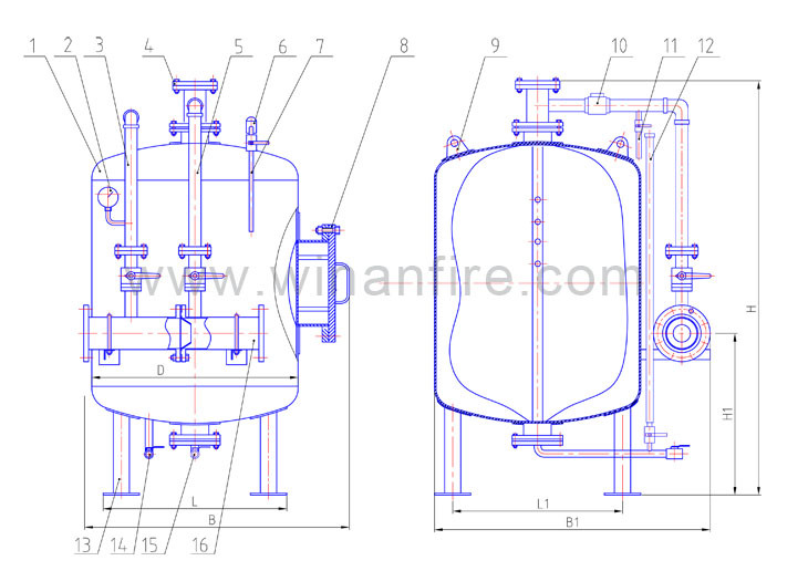
1. Tank   2. Pressure Gauge   3. Water Inlet Pipe   4.Feed Inlet   5. Concentrate Outlet   6. Safety Valve
7. Tank Vent   8. Inspection Hole   9. Lifting Lug  10. Check Valve  11. Bladder Vent
12. Liquid Indicator   13. Bracket   14. Water Drainage Valve  15. Foam Drainage   16. Proportioner
Â
| CAPACITY LITERS | D mm |
L mm |
L1 mm |
B mm |
B1 mm |
H mm |
H1 mm |
WEIGHT (KG) |
| 500 | 800 | 810 | 600 | 1000 | 1150 | 1700 | 1200 | 280 |
| 1000 | 1000 | 1010 | 800 | 1200 | 1350 | 2100 | 1200 | 350 |
| 1500 | 1200 | 1210 | 1000 | 1400 | 1550 | 2100 | 1200 | 450 |
| 2000 | 1400 | 1410 | 1200 | 1600 | 1750 | 2050 | 1200 | 550 |
| 3000 | 1400 | 1410 | 1200 | 1600 | 1750 | 2450 | 1200 | 800 |
| 4000 | 1600 | 1600 | 1400 | 1800 | 1950 | 2800 | 1200 | 1050 |
| 5000 | Marble Sculpting There are many ways to design stone carvings. Relief: carving a three-dimensional image on the stone surface, which is a semi vertical sculpture. Because the image is embossed on the stone surface, it is called relief. According to the depth of the stone surface, it can be divided into shallow relief and high relief. Shallow relief is a single level statue, which has a single content and is not hollowed out. High relief is a multi-level sculpture with complicated contents. It is more attractive to use openwork techniques to hollow out. The reliefs are mostly used for the wall decoration of buildings, as well as the dragon columns and holding drums of temples. Marble Sculpting,Marble Sculpting Process,Modern Marble Sculpting,Marble Sculpture Art The universe in the stone is great , https://www.zdartwork.com |